
18s2p VESC DIY One Wheel Build w/ Hypercore | The Red Pill, a.k.a., the Kev Special | A Project Log
When building a project like this, it’s important to bench test as many things as possible before committing to an assembly. The motor should be run through detection while bolted to a bench, the VESC should be checked with that as well. The wiring adapters should be used to bench test foot sensors, lights should be hooked up and checked if they work. Anything that would be a problem to get to when the project is finished, should be bench tested. Skipping that, especially if this is a new style of project, may lead to big headaches down the road.
0. Introduction
This is currently (as of late 2023 - early 2024), the “most juice for the squeeze” build/conversion type I’ve done. It essentially takes the body of a Onewheel XR, removes the electronics core (front and rear enclosures) and replaces it with new custom assemblies that are put together from a variety of products made from a variety of vendors.
This log details such a rebuild/conversion that I did for a local rider friend with an old XR that was in disrepair, and very long in the tooth. With this new rebuild of electronics, the board has a new life, but still retains some of the old soul of the XR ride feel that is hard to beat.
This is the end result, and while the internals are all new, the outside is still a “worn in” aesthetic, since the outer frame was very much a lived-in kind of board.
I call it the “Kev Special” because a friend of mine was one of the first people in my area to ask me to take his broken Onewheel XR and replace the internals with this kind of setup. He has one of the first ME4T Packs in New York, and his setup has been the guiding light for where this project mindset has gone, specifically the most accessible goal of an 18s2p ME4T Pack battery with an XLITE BMS, WTF rails, Floatboxx front enclosure, Hypercore motor, etc. He’s a very curb nudge focused rider, and his street riding has been a constant testament to the robustness of this build scheme.
The “red pill” part, is that since this is a pretty direct internal swap for an old XR board, it’s a more digestible VESC conversion experience for DIY builders to approach. DIY and custom building is itself, difficult and complex at times, however this particular kind of project retains some familiarity with the original board, and so it becomes less intimidating for folks to come to.


1. The Old Parts
For this project, the parts from the original board that were kept were as follows:
Hypercore motor (tire was changed)
Rails (older Float Life WTF rails with rail guards of some kind)
Footpads (front sensor pad and rear footpad, both with a foam grip tape of some kind)
Front bumper (Float Life BANG Bumper)
The rear bumper in this case was replaced with a Float Life / Badger Wheel TORque bumper, in order to accommodate the larger TORque box, which was needed to house the new, larger, 18s2p ME4T Pack that I make in house. Fortunately, I still have a few of the matte black ones, and so it easily matched the matte black front BANG bumper that was already in use.
In a case like this, the owner of the board could sell the older electronics and enclosures if some parts are still working, to a repair shop that could repurpose those parts in a refurbishment or repair of other devices.
2. The New Parts
Here is a list of the major new parts from independent vendors that was used to complete this project. Do note that in some cases, these parts may be found from their makers directly, or from other vendors that collect them and offer them in a kit. My shop, for example, will be offering some kit options this year (2024) that include the battery, BMS, and enclosure, as well as wiring. Depending on when you’re reading this, those options may be available. If not, they can be obtained from those vendors directly. Be sure to check the store here, as well as the stores of the vendors mentioned in this log, as that’s where I would have gotten them for such a project.
Also note that this list does NOT include the odds and ends that are needed for the assembly, such as adhesives, certain specialty washers, tapes, etc. Those items will be shown and detailed in the log itself and the photos.
Floatboxx MLC Aluminum VESC enclosure (Front box)
Badger Wheel TORque Box (Rear box)
Floatboxx 12-core Cable (Discontinued, but replaced with new 14-core cable that was done in collaboration with me at The Board Garage; These will be in stock soon)
Little FOCer v3.1.1 VESC from Shaman Systems
ENNOID XLITE V3 BMS
18s2p 50S ME4T Pack (one of the packs I make)
6-Pin Molex to 4mm Bullet Connector Adapter (I make these when I need them, details in the log)
Switchcraft to JST Adapters (same as above, I make these as needed for footpads and motor plugs, details below in the log)
Arduino-based Lighting Setup (separate log article on this, as it’s a bit complicated)
3. The Front Enclosure/Box (Floatboxx MLC)


The above photos are the more or less end result, so that there’s some perspective of what’s being worked towards in this project. If you’re familiar with VESC one wheels at all, you’ll probably recognize the Little FOCer VESC, and the connectors for the Hypercore motor and foot sensor.
The photo gallery below will show the first few connectors and adapters added to the Floatboxx MLC. The Floatboxx is an aluminum enclosure made for these kinds of projects, and acts as the box and heatsink for the VESC. The black uncoated surface is where the thermal pad sits, and the VESC is mounted to the posts in order to transfer heat from the MOSFETS (the electronics switches that run the motor, and therefore get hot).


The Hypercore motor found on the XR and Plus models uses 2 separate motor connectors. The larger is a Molex MX 6-Pin, and the smaller is a Switchcraft 6 pin connector. The Molex is used for the phase wires (the main power wires) and the Switchcraft is used for the sensors (hall sensors, temperature, etc.). For anyone who is already familiar with the Flowglider style box, the Molex here may look different, and it is. This version uses crimp connectors that slide into the Molex housing, click in, and then get secured by the white internal piece that closes inward.
Note that since there are 6 pins in the Molex, and 3 motor phase wires at the VESC, the pins get paired up in parallel. This is done VERTICALLY, as can be seen, and matches up with how they are on the motor plug itself. Then, the two wires get joined here at a 4mm Amass Bullet connector via the solder cup.
When mounting to the Floatboxx, the Molex sits on the outside, and gets bolted on with M4 nylock nuts with washers underneath. These Molex connectors normally include a rubber gasket, so that would sit between the Floatboxx and the connector housing.
The parts are as follows:
Connector: Molex Part # 19429-0044
Crimp Pins: Molex Part # 19417-0025 (gold plated) <- Note that the number may change if it’s loose, this is for cut strip pieces.
Motor Sensor & Footpad Connector: Switchcraft Part # EN3P6MX
4mm Bullet Connectors: https://amzn.to/48ZX8Ky
Also, below is a series of images of how the Switchcraft connectors are wired for the footpad sensor and motor sensor. I did my best to show how the result looks on these specific panel mount pieces.
THE LAST TWO IMAGES ARE MIRRORS OF EACH OTHER, THE LAST IS THE MOTOR PLUG, AND IT MATCHES UP WITH THE WIRING OF THE PANEL MOUNT SHOWN BEFORE IT.
THE MOTOR SENSOR JST-PH 6-PIN CONNECTOR FOLLOWS THE SAME MOTOR SENSOR PIN ORDER AS MOST PEV MOTORS AND VESCS.


Cable Gland
You’ll notice that the power cable for this enclosure is passed through a metal cinch nut, or cable gland. The size is M20, and as far as I’ve experienced, they are sold separately from the actual lock nut that tightens it to the panel.
The one I used here is an Altec brass gland, however it’s not actually difficult to source an M20 cable gland. When in doubt, know that Floatboxx sells one thats particularly compact, and it’s actually at a reasonable price, since it includes the lock nut.
https://www.floatboxx.com/product/10039957/m20-cable-gland
As 2024 goes on, I’ll be expanding my shop’s offerings to include these products, so they can be available in the US with domestic shipping. Hopefully by the time you’re reading this, that will be in motion.
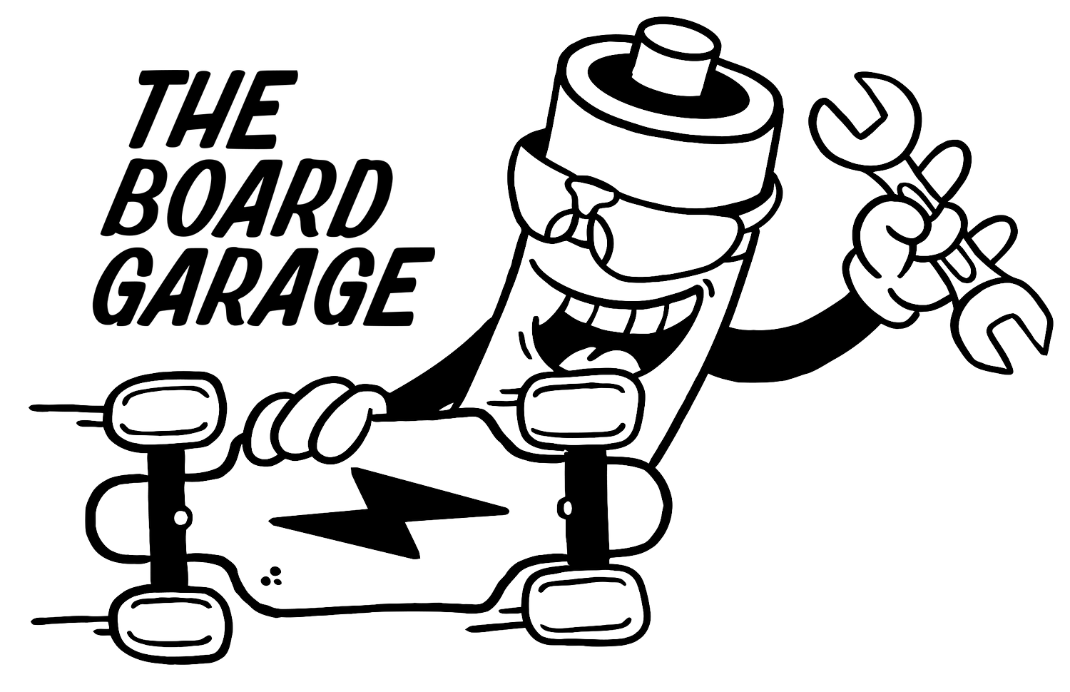
The Charge Port
Note: This project uses a “charge only BMS”. That means that the BMS only manages the charging of the battery, and does not engage with the power being discharged to the VESC. There are reasons for that, which are more appropriate to be discussed elsewhere. The point is that the charge port wiring goes directly to the BMS in the rear. And there is no shared connection between the charge port and the VESC. They are totally separate. This is why you’ll see the charge port goes to the wiring harness, and that goes right to the BMS.
Charge ports are sometimes a bit of a tension point for some builders, and there currently is no real standard within the DIY/Custom VESC one wheel space. So, the charge port can be wired however the builder chooses. What matters is that it matches the charger plug being used, and that the positive and negative wires from the port go to the right place.
This particular charge port is an XLR 4 pin, which I chose in case the user still had regular Onewheel XRs laying around, and so it would avoid an errant charge plug in. I wired it with the positive on pin 1, and the negative on pin 4 (because it’s on the other side). The port itself terminates in a male XT30, in order to easily connect to the wiring harness that will be shown later. The more commonly used charge port is a 3 pin XLR.
4 Pin Charge Port: Neutrik NC4MPR-HD (NC4FX is the mating charger plug)
3 Pin Charge Port: Neutrik NC3MPR-HD
Within the charge port positive wire, I put a 120v/10a fuse. I don’t expect the charge speed of this project to exceed 6 amps, and so the fuse is properly spec’d for a 75v board with a charge rate of 4-6 amps.
Fuse: Littelfuse Inc. 0251010.NRT1L
The third image below is a different project, so ignore the spacer ring. However the charge port itself is the same.


The Power Button
The power button is a fairly simple 19mm latching button with LED. The Little FOCer uses a reverse switching logic, where the pins are open for the VESC to turn on, and the switch pin shorts to ground for it to turn off. Depending on the button you choose, you’ll have to use a multimeter in continuity check mode to find which pins allow it to be conected when the button is pressed in. Usually, this is the Normally Open (NO) pin across to the Common (C) pin.
If you look at enough of these kinds of buttons, it’ll begin to make sense. But, some vendors also just sell these power buttons for the Little FOCer.
In these cases, the Common (C) pin on the button is also shorted to Ground (-), so I just wire a little parallel Y shape with the wires, seen below with the black wires and red heat shrink.
Again, the third picture below is of a different button from this particular project, but it illustrated the whole thing.
Power Buttons:
https://amzn.to/3HsredS


The Lights
This board has an Arduino based lighting setup that changes colors directionally, shows the battery level when idle, and activates when you step on the foot sensor.
The details of the lighting setup and its parts will be detailed in a separate article, so be sure to check the articles section of this site for that information. It will log how I put together the wiring for the Arduino, the voltage converter, and where the code came from (Mitch Lustig, the godfather of the Balance Code for VESC wrote it).
Aside from that, the headlight for the Floatboxx is housed in a separate part. The holder itself is a 3D printed piece, which I printed in polycarbonate (PolyMax PC) on my Bambu X1 Carbon. There is a file for it, sized for LED sticks like the Neopixel, on the Floatboxx website. The one I’m using here, is actually a remix of that file, done by Eric Ugland, who makes his own light controller for VESC projects. His is a bit more basic, but has been positively received, and he was kind enough to publish the file for his LED holder for the Floatboxx.
https://www.printables.com/model/511192-floatboxx-led-holder-sk6812/files
https://www.ugland.camera/vesc
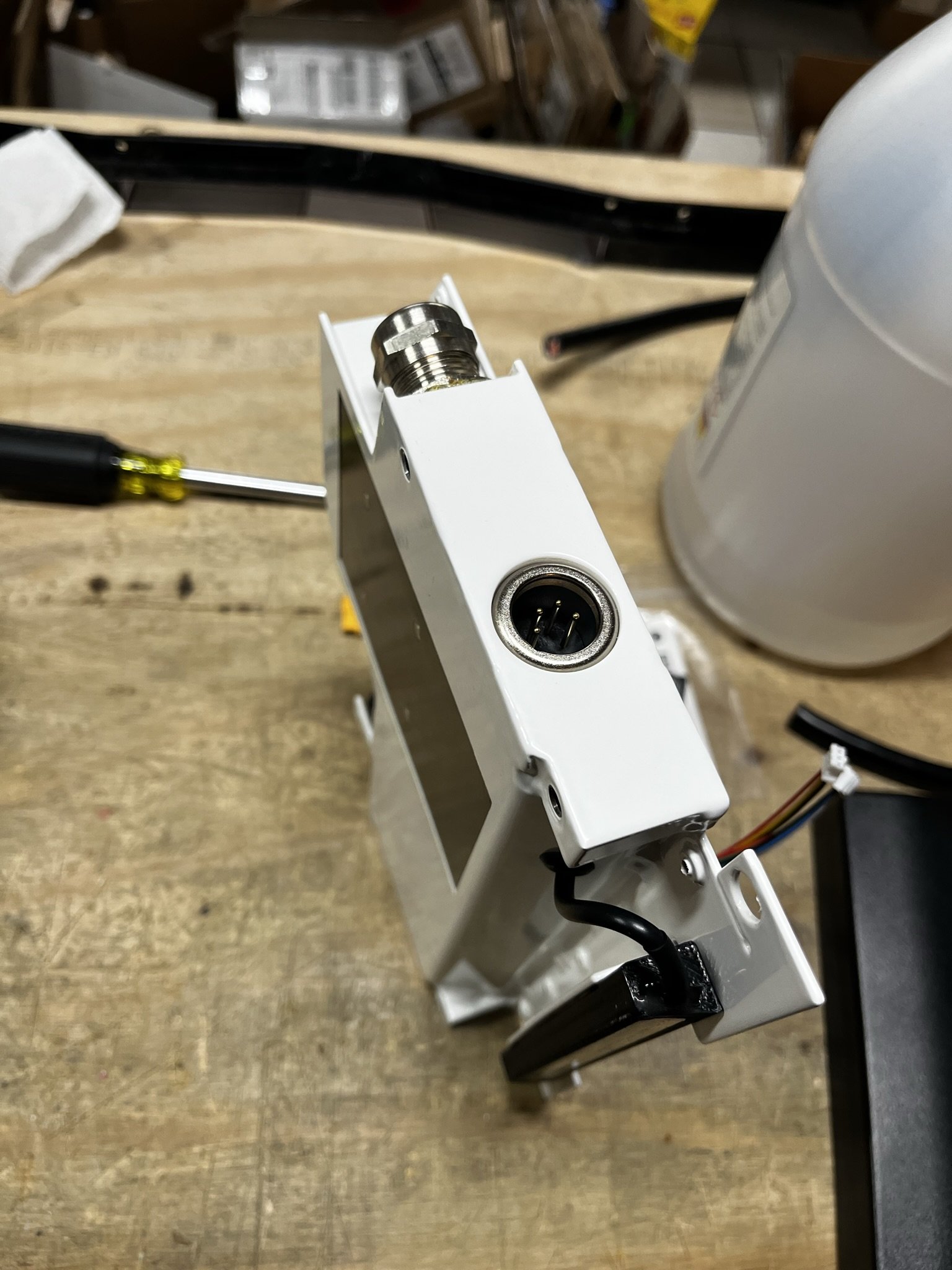
Below, you’ll be able to see the LED strip holder, as well as the cable I used. It runs into the Floatboxx through a rubber grommet instead of a cable gland. I don’t know the actual size, as it came from an assortment kit. I will link the items I’m using here below the photos. Notice that inside the box, the light wires are terminated in a 3 pin male JST. This will mate up with the female JST from the lighting setup.
After the LED strip was wired, I potted the entire thing in a clear epoxy which seals it up, sinks away heat from the full bright LEDs when running, and holds everything in place. Many thanks to Joe Z from Z Battery Solutions for the recommendation on the epoxy.
Whether it’s the Floatboxx file, or the Ugland file, the LED strip holder is attached to the Floatboxx via 2 screws. What I did is to drill out the holes a bit, and use M2.5 heat press inserts. I then used a strip of VHB at the part where it seats against the handle flange of the box, and adhered it along with the screws holding it on. This helps it be pretty robust, while still generally removable in case the headlight breaks.


LED Strips: https://amzn.to/3U4ugfX
3-Core Cable: https://amzn.to/47HM43I
PC Clear Epoxy: https://amzn.to/3SpUGaF
The tail light seen above is the same kind of LED strip as the head light, but it will be covered in a later section with the rear battery box.
FOCer (VESC) Installation
Please note that I installed the VESC into the Floatboxx AFTER I did the wiring cable connectors and installed it into the Floatboxx.
When mounting the FOCer to a metal heat sink surface (like the floor of the Floatboxx), there are some important things to remember. It has to be distanced from the metal surface, as well as insulated against that surface. The idea is that the MOSFETs have a thermal interface between them and the heatsink, so gaps are filled and heat can transfer. Also, this thermal interface needs to be as thin as possible, without the exposed surfaces of those MOSFETs touching a conductive surface and causing a short.
If you order a Floatboxx, you’re provided with some small nylon washers that are 0.5mm thick.
When these are placed on the mounting posts, you can then cut an appropriately sized piece of thermal pad to cover the area the MOSFETs will touch, using a thermal pad thats 1mm thick. Once the VESC is bolted down onto those posts, the thermal pad will squish, and the 0.5mm washers will stop the MOSFETs from fully touching the metal surface.
Another step I take in this project (and in others that are similar), is to use a nylon bushing washer under the nylock nuts, which sit around the post, between it and the PCB, as well as under the metal nut.
Once again, the last picture is from a different project, but it illustrates things a bit better. Note the thermal pad, with circles cut out for the 0.5mm washers. I used an art knife for that (or an XACTO), but some folks mentioned a plastic drinking straw works to punch the holes. You can also see the bare MOSFET metal, which is what was mentioned earlier.


The bushing washers can be found online in large quantites (usually 1,000 pcs), however I also sell some in my store in smaller quantities, basically for the price of postage and the packaging in case you don’t want to deal with 1,000 of them. If you’d rather source them yourself, they are the TO-220 bushing washer.
Thermal pad recommendations:
These are thermal pads I’ve all used for VESC projects, and they’ve all performed well. I have not A/B tested them, so I can’t provide a chart of their temps, but they’re above the 12.8w/mK (that stands for watts per meters Kelvin, btw) that should be used for this type of thing. Your mileage may vary.
The Floatboxx includes foam pieces. One of them is custom cut to be put on the underside of the lid. This is obvious since it’s packaged with the lid itself.
4. Wiring Cable / Harness / Connections
Connectors used:
XT60: https://amzn.to/48xPIOJ
XT30: https://amzn.to/48Gn1PL
JST-PH Kits: https://amzn.to/3U46P6r & https://amzn.to/3SaptH4
JST-SYP Kit: https://amzn.to/3vFxUCB
Crimping Tool: https://amzn.to/3S5FkH0
The main power cable used here is the Floatboxx 12-core cable, which is a single piece item that then gets stripped and terminated to suit the project’s needs. The 12-core variant is currently discontinued, however it was replaced with a 14-core variant that was specified to accommodate a split pack battery build, with color coded wire.
That cable is something I sell in my store, and I’ll be ordering more of it in as well, so that’s someplace to look. If it’s not available at the time, it is sold by Floatboxx, and could be ordered with the Floatboxx enclosure itself.
The difference between the 2 is mainly some wire gauge changes and the addition of extra wires. The ones needed for a regular battery setup are all still there, and so these connections would still apply.
Front Wiring Connections
Notice above that there are twisted pairs of small wire, and those are meant to go together for things like CAN Bus and other data hookups. The main power input to the VESC is handled by the largest wires, and they terminate in that female XT60 connector. Notice also that there is a pair of wires paralleled off from that XT60. This is for the voltage buck converter (or step down converter), which gets its power input from the battery as well. The red connector is a JST-SYP, and I have them in the shop from older Meepo Board repairs, as that was the charge connector on those old brick packs. They work well, and the current to the buck converter is pretty low as it is. Since that connector is energized (from the battery), it’s the female end.
This is a reason why I moved over to the regular XT60 connectors, and not the XT60H with the plastic housing cap. I’ve found that those will make it much harder to parallel off the wires needed for the buck converter. So instead I used a regular XT60 here and used heat shrink.
I think it’s important for connectors/plugs that have active voltages across their +/- pins to be female ends, to reduce the risk of contacts touching/bridging and causing a short.
Also on this cable is the charge circuit. Note that it terminates in an XT30, a female in this case. The charge port used a male XT30, and so this mates to that.
The smaller wires are as follows:
Blue/White Pair: CAN BUS Data (between VESC & BMS)
Brown/White Pair: CAN Wake (5v/Grnd Auxiliary from VESC to wake up the BMS when board is on)
Green/White + Orange: Tail light wiring (for 5v, Grnd, and Data from the Arduino in front to the LED strip in the rear)
Those are all standard JST-PH connectors (2.0mm pitch), and they’re pretty easy to source. If someone is into DIY building and projects, or has to do similar work, then it’s a decent idea to have a kit of those connectors and crimps. These are the sorts of things I crimp myself, and crimping gets easier the more it’s practiced.
The location of the wires on the connector can usually just be seen on the pinout diagrams for the Little FOCer, as well as the BMS in the rear. Those diagrams are almost always available on the site where they’re sold, or by a simple web search.
For clarity though, below is the pinout diagram of the Little FOCer v3.1, and so it should illustrate the connectors I’m using for the CAN bus and Aux Power, for example.
AN IMPORTANT NOTE: PINOUTS ARE KEY, AS ARE UNDERSTANDING WHERE EACH WIRE GOES. COLOR CODED WIRES AND CONNECTOR POSITIONS ARE TOOLS TO HELP UNDERSTAND THAT QUICKLY, HOWEVER IT IS THE RESPONSIBILITY OF A BUILDER TO UNDERSTAND WHICH WIRES ARE GOING WHERE, AND MAKING SURE THAT THINGS LINE UP PROPERLY.
FOR EXAMPLE, THE WIRING USED FOR THE REAR LED STRIP HAS GREEN, WHITE AND ORANGE WIRES. THE LED STRIPS THEMSELVES HAVE RED/BLACK/YELLOW IN FRONT, AND RED/BLACK GREEN IN BACK. I MADE MENTAL NOTES OF WHAT CABLE WIRES WENT TO WHAT WIRE IN THE REAR, AND KEPT THEM SORTED. OTHERWISE, COMPONENTS GET DAMAGED.
Rear Wiring Connections
Above is the image of the TORque box, with the cable threaded through another M20 cable gland. That gland in particular has the same sized lock nut, but for many of them I find myself having to grind down a couple of surfaces to get it to fit into the caputure slot of the TORque box. It’s not a terrible task, since I use a disc sander for it, but it is something I have to keep in mind whenever I use a TORque box.
Specifically here though, I matched the wiring connections from the front, to where they’ll need to go in the rear. The charge circuit that I know is coming from the charge port, is terminated here in an XT30 male, which will connect to the BMS’s charge input. The wires were left at the appropriate length for that.
The XT60 is terminated in a male as well, since the discharge connection from the battery is a female XT60 (since it’s energized).
The CAN Bus connection is in one single female 4-pin JST-PH, and that mates up to the CAN Bus header on the BMS. The BMS used is an ENNOID XLITE V3, and the pinout for that is available on the site. But, here’s that pinout anyway:
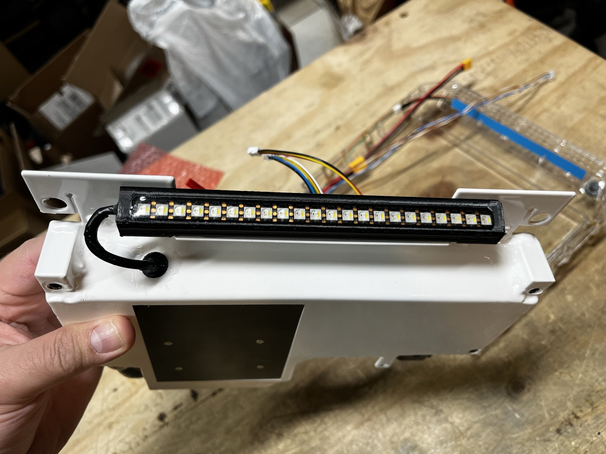
5. TORque Box


As seen above, I did install a tail light in the TORque box. A window isn’t needed obviously, because the whole thing is a clear injection molded polycarbonate. The LED strip used here, is the same as the head light. It is cut to 22 LEDs in length, and the 3 wires are soldered to the little pads on the LED strip.
As mentioned previously, the lighting setup will be detailed in a separate article, but this should give a picture of how it’s mounted.
I did have to cut some of the wings in the box, specifically at the window. This is so they would line up with the remaining wings, that sit between the LED dies. There are also larger retention wings that help hold the LED strip in place.
There are about 4 little blobs of the clear epoxy that secure this in place. It’s not the most ideal solution, but it’s the best I could do with this particular box, and so far I have not actually run into issues with this LED strip in this use case. If I did though, the little epoxy blobs can be cut out/off with a pair of small flush cutters, the surface cleaned up a bit, and the LED strip replaced. It would be a process, and probably not a fun one, but it could be done, and I tried to set it up this way, just in case it needed repair.
This is also a good reason to BENCH TEST things before committing.
I will go into detail with how I set the LED strip in the box, in the other lighting article. But essentially I clipped the wings in the box as needed to align the strip towards the left (checking for the rear bumper cutout to line up), and then set the strip in the epoxy blobs, and used Kapton tape to secure it while it cured.


Above are some photos of bench testing the lights, configuring them, etc. Note that I did all this before things were secured and adhered down in either the front or rear box.
Above is a picture of something I made a long time ago, for bench testing VESCs and other ESCs with an XT60 connector. They convert the XT60 to XT90S, so that the anti-spark resistor can be used, removing the inrush current spark that happens when connecting a power source (battery) to a source of capacitance (the ESC).
I also use this when I’m connecting the battery during assembly, to pre charge the capacitors in the VESC without the spark. After that, I’ll remove the adapter and connected the XT60s as needed.
Battery & BMS Installation
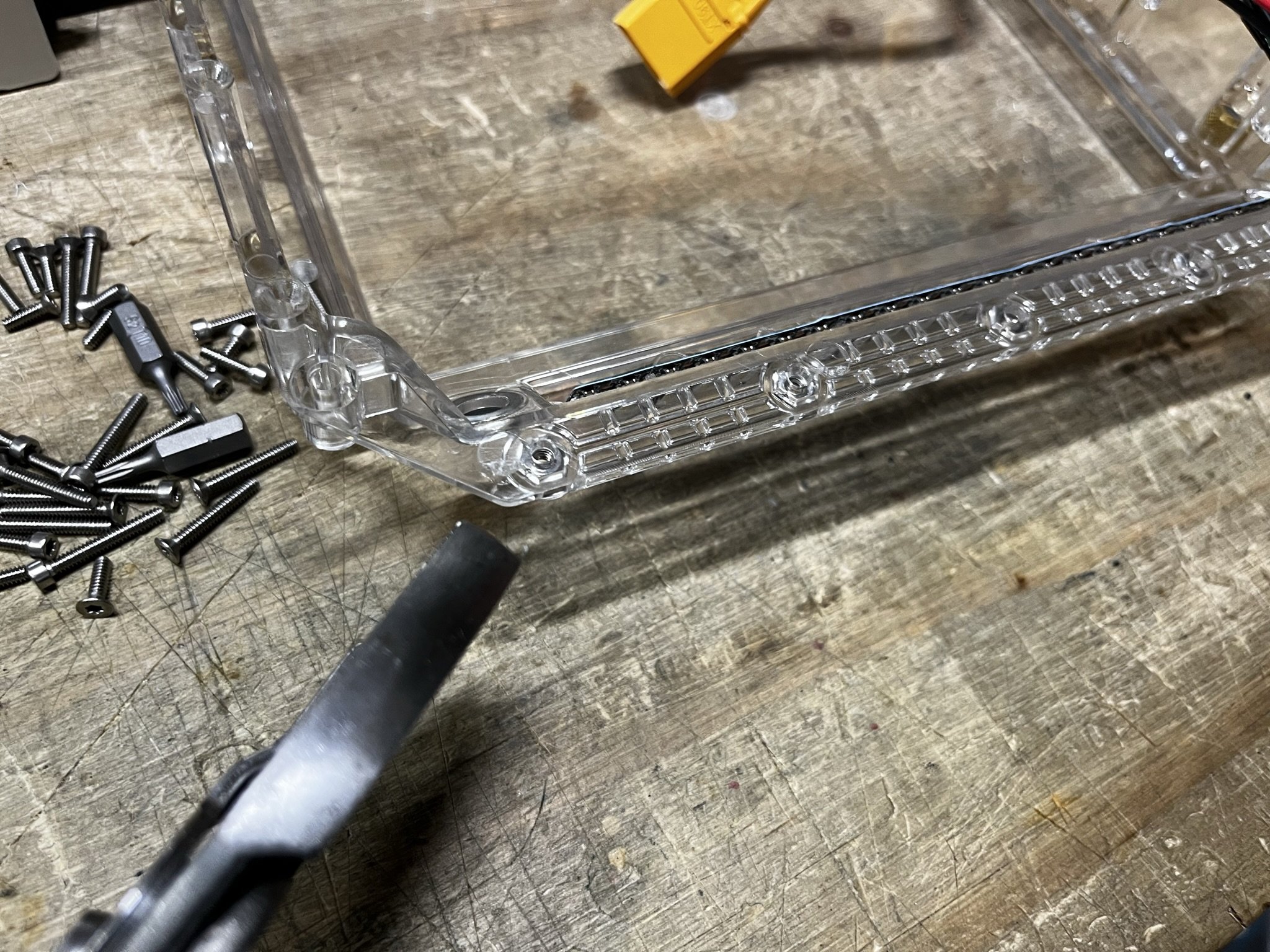
Before anything electrical gets into the TORque box, I like to set and align the rear hex nuts that the lid screws will go into. This is actually kind of difficult, since the rear lid screws are 1/4” long (check that they are, because longer screws will interefere with the TORque Bumper). The short screws don’t grab the hex nuts unless they’re actually fully seated, and seated flat.
Also, since they’re very stainless steel (yes, very stainless steel), they’re soft. So they can strip and break more easily than harder screws.
One way that I have done this, is to press the hex nuts into the box with some pliers, and then use one of the longer cap head screws to pull it straight into the pocket.
BE CAREFUL WHEN DOING THIS. The box can crack if done too hard, and the screws can cross thread if they are inserted crooked. The image below shows a shorter screw being used to do this, but the longer screws will be easier to align, and not cross thread.
PROCEED WITH CAUTION.

Also, the rear short screws do go into a metal nut, and they don’t have the same kind of thread resistance as the screws cutting their threads into the polycarbonate box. I have seen instances where these rear screws loosen.
For these, I would use this thread locker, Vibratite VC-3: https://amzn.to/3S5dLO8 since it is not the same anaerobic type as regular ble Loctite. It is instead, a resin based substance, that you apply to the threads and let dry. Once dry, it acts like those nylon patches that are on some screws. This will hold the screws without possibly damaging any plastics.
Fish paper is a go-to insulator when I’m not sure what my other options are. For this reason, I cut a length of it and folded it into a barrier/shelf to sit on top of the LED strip in preparation for placing the XLITE into that sloped area at the rear of the TORque box.
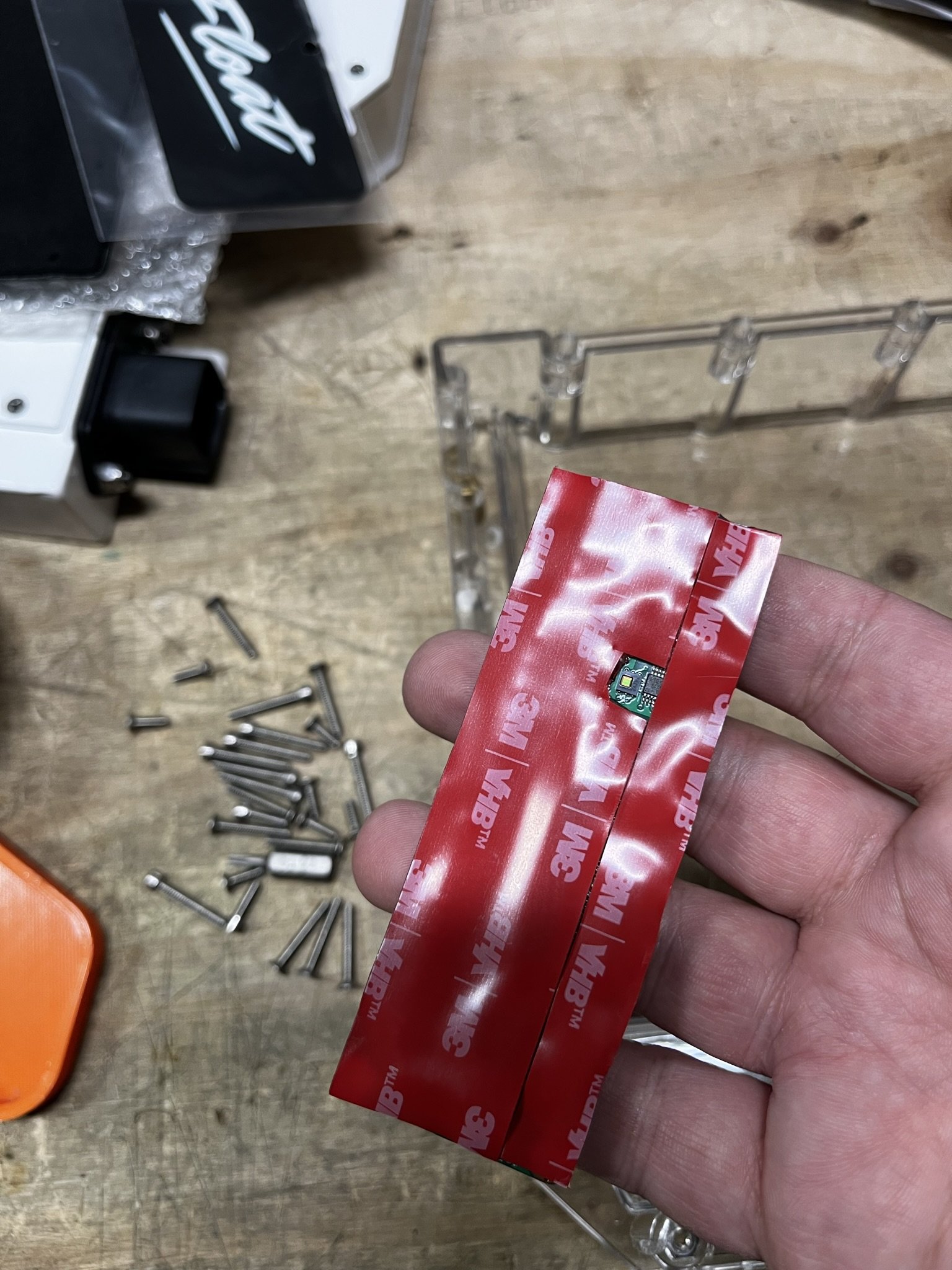
The XLITE itself gets a small strip of TESA Tape (https://amzn.to/48DFlsE) to cover over the face of it, since the wires are going to sit there and likely be compressed when the lid closes.
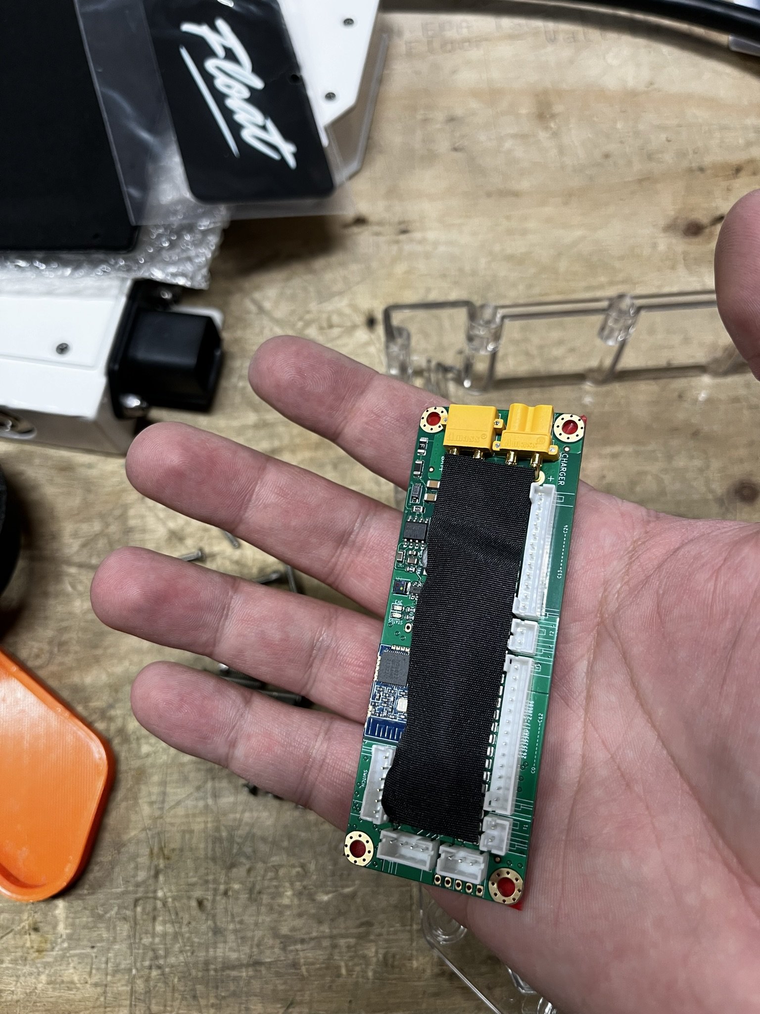
On the underside of the XLITE, I actually clip some of the legs of the headers off to make it slightly flatter. There’s usually one long leg, from the buzzer that sticks out quite a bit. The rest aren’t necessary, probably, but I trim the legs of the balance connector headers a bit just in case they decide to poke down through the VHB into the LED strip.
After that, I place clear VHB (https://amzn.to/47Is7tt & https://amzn.to/47IkpQ2) on the underside, leaving a cut out for the humidity/temp sensor. Covering it over tends to mess with the readings in the box.

Once that’s all done, I place the pack into the box, check the fit, and then begin managing the wiring. I’ll do some dry fitting and test placement of the BMS, and make sure that my wiring harness connections reach where they need to. If not, I’d need to fix that before committing to a location for the install.
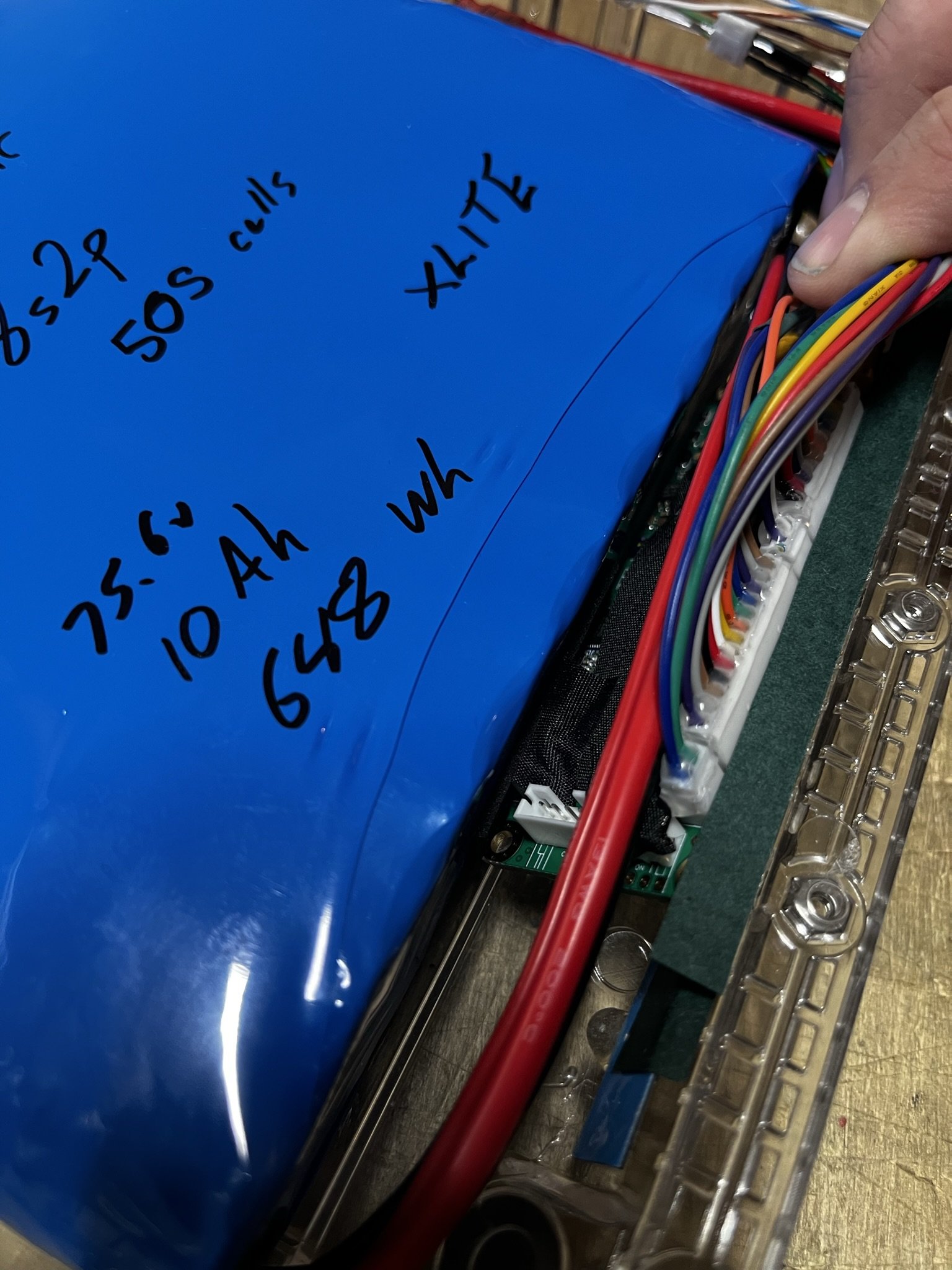
The ME4T Pack (https://theboardgarage.com/store/p/18s2p-50s-cells-custom-battery-for-vesc-onewheel-builds-conversions) sits nicely in the TORque box, and the XLITE essentially butts up against it.
There are some points to be aware of, that I’ve learned over the last several months, and I will do my best to detail them here.


In the above first photo, I’m pointing at the 3.3v inductor on the XLITE V3. That little cube gets very close to the battery pack, and if it touches it directly, it’s at risk of being knocked off the PCB, and your BMS will no longer work. It won’t likely become dangerous, but it will no longer wake up, charge, or do anything. In fairness, a BMS failure, especially for a charge-only BMS, should result in it just not turning on anymore, since its only job is to manage charging. If it’s broken, and doesn’t charge, then that’s a positive.
Anyway, as far as mounting the BMS goes, I have personally found it a good idea to make sure that this component has a bit of space from the face of the battery pack.
A note on that: On my batteries, there is a length of fish paper on the BMS-facing side of the battery. It’s below the blue heat shrink. This is just in case the closing pressure of the lid, forces the edge of the BMS too far into the pack if it was installed wrong. I haven’t seen it happen yet, but, I just figured there may come a time when a BMS just jams right into the pack and wears through the insulation or mounting scheme.
And since I don’t ever want to open up a board again, or have someone else need to open their own projects again, I stick that there in case, to avoid extra risk.
Back to the XLITE mounting here. I put a small piece of foam on the left side, near that JST header where it touched the pack. Also, there is a small spacer I made out of fish paper, that’s about 10 layers thick, and cut to a neat square. It sits on the right side corner of the XLITE, where the XT30 headers are (those yellow things on the PCB), and space it about 1.5mm off the face of the pack. That generally seems to be enough to keep the little cube where it needs to be.


Once that stuff is taken care of, I’ll connect the BMS to the battery, and line the wires up where they need to go. Before anything gets folded down, I will run a thin bead of hot glue along the JST header where it meets the balance connector. This helps keep the connectors seated properly, in case the rest of the install gets a bit hamfisted.
After that, I add a small strip of the TESA tape over the open JST headers on the BMS. Open pins next to balance wires tends to scare me a bit, so I cover over that sort of thing when possible. The balance wires get neatly rolled over the discharge and pack wires, and the CAN bus wires get routed under those as well.
Once that’s done, I lay a long piece of Kapton tape across the rear corner of the pack, in order to prevent any balance wires from getting on top and sitting above the top plane of the battery. Then a second piece goes over the wires and connectors to seat it down. I’ll then run one more piece lengthwise over the wiring entering the TORque box, making sure that the connectors and wires have free space and clearance and don’t pinch in any way.
The charge input would have been plugged in from the wiring cable before this happens, by the way.
Lastly, a thin strip of fish paper will sit on the corner of the BMS, to keep that edge of the PCB from wearing through the lid’s foam and hitting a metal surface. I’m not sure if this is necessary, as ideally, that BMS edge should sit at or below the rear lip of the box. But, nothing is perfect, and it’s a precaution I feel I need to take.
Editorial
I’ve seen an experienced Onewheel tech completely botch an install (more than once, actually), and the balance connectors pulled out a bit, and lead to scary cell readings in the BMS. So…you know. No one is above doing the wrong thing. Caution and arrogance usually don’t go together. I tend to no longer trust techs and builders who toot their own horns too loudly. While cliche, more often than not, it’s to compensate for a lack of hard earned expertise. And I’ve found that this hobby is littered with folks who fancy themselves more skilled than they really are. Myself included at times. I’ll often have to catch myself resting on my laurels, and really make sure that I’m doing things the way I’ve come to expect from myself, even if the friend/rider/customer isn’t ever going to see it or I’m not going to post it to any socials. It’s often the fear that my work will fall short, that informs my constant second-guessing. Probably not great for my health, granted.
/Editorial
Note that for the 18s2p pack in the TORque box, there’s been no foam padding added under or around the battery. There simply isn’t room for it. Adding that could lead to excessive compression of the pack, and the compression of the foam would render any padding completely useless. It just won’t do anything. The pack fit is tight already, and so it has a “compression fit”. It’s not going to move in the TORque box, because it takes a bit of a squeeze already.
My current understanding is that adding foam is just a placebo, and may (I’m guessing) do more harm than good. But, you do you. I’m just logging what I did for this project.
6. The Main Core Assembly
When the enclosures are done (generally, I’ll leave the rear box for last), then what I have is the main assembly, or the core. If there were a random Onewheel XR sitting around that didn’t work, this is the big collection of parts that I would swap in to make it run. So once that’s achieved, it’s just a matter of installing it into the rails, and putting the board back together.


Do note that the Floatboxx is a European product, and so the screws and fasteners it uses are all metric. This hasn’t mattered up until now, since the included screws are all just going into its own parts. HOWEVER, the Onewheel XR body screws are historically SAE, specifically #10-32 (I think…) screws. This means that the usual rail screws and bumper screws that go into the Floatboxx, won’t fit.
The Floatboxx includes screws, and so a total of 4 screws on the assembly to the rails and bumpers, will be metric. They will be stainless steel, whereas the rest of the regular XR screws will be black oxide coated alloy steel.
The above is metric, as can be seen. Also note that the screw hole to the left of it is the front corner bumper screw, and so one of the long metric screws included will need to go there when installing the bumper.
7. Final Assembly
Getting the rest of the board together is essentially just putting a Onewheel XR back together. Mount the motor, get the footpads and bumpers on, etc.
However, there are 2 points of note that are important.
First is the connector cover. The Floatboxx includes one, and it secures in 2 ways. The first is a threaded post that you then install a nylock nut to. After that, it has wings that sit in the rail pockets where the old connector cover would go. Not below, there is a post and nylock nut in the connector cover.
I line the connector cover with thin foam, since a square of it is included. It’s not visible in the photo below, so I’m sorry about that. It’s underneath the bottom edge of the box. However, this foam is necessary in my opinion, as there are vibrations and resonance frequencies that occur when braking hard, and this leads to phyiscal vibrations of the metal parts. The foam removes this, as those vibrations are a problem.
Also, very important, is that if you’re using a regular wooden footpad in the rear, or any thin footpad, that the screws used are the shortest length available in Onewheel screw kits. Long screws pierce battery boxes in general, and the same is true here.
In this PARTICULAR project, the rear footpad was a Float Life Kush Pad, and so a metal support plate was used, to help reduce the amount of direct rider weight that gets to the lid of the TORque box, and therefore the battery itself.

