

Onewheel GT Battery Re-Wiring; for ENNOID XLITE V3
If anyone is unable or unwilling to read through this article in its entirety, and is not familiar with the points of note in the log, then they should not attempt such a build/project/repair. Lithium-ion batteries are inherently dangerous, and to work on or with them properly takes understanding and skill that is not easily acquired.
One of the most dangerous forces in this hobby is false confidence, and a desire to do something regardless of the limits of one’s skill.
Recently, I was sent the battery pack from a Onewheel GT, to have the wiring redone for an ENNOID XLITE V3 BMS, for use in a DIY, VESC-based conversion project. The battery was in good condition for all I could tell (electrically and physically), and so it was just a matter of having it able to be charged through XLITE.
With the older Onewheel XR platform, the projects I’ve seen using the stock battery tend to use some kind of breakout PCB, that adapts the JST-ZPD connector to through holes, for soldering to a shortened version of the more standard JST-PH connectors used on BMS units like the ENNOID XLITE and the ZBMS.
This is an easier way to implement a stock Onewheel XR battery into a different charging setup, however the breakout boards I’ve seen so far don’t have traces for the temperature sensors. In-pack temperature sensors are themselves a bit of a topic of debate and discussion (the details of which aren’t the focus of this article), but I tend to like putting them in, especially for projects like these where the use case a bit more novel and so the performance and life of the battery is going in to uncharted territory.
When I say uncharted territory, I’m specifically talking about power demands from a battery that was NOT designed to handle them.
Just like the stock Onewheel XR battery, the stock Onewheel GT battery IS EVIDENTLY NOT DESIGNED TO HANDLE HIGHER POWER DEMANDS THAN WHAT WAS DESIGNED INTO THE ONEWHEEL GT BOARD. < This is my opinion based on the findings from opening up the battery and looking at common choke points for performance that require workarounds when making a battery for DIY devices that will demand more power than mass production equivalents.
There are a couple of rationales for my saying that, and I will do my best to illutrate those in this log.
To start, I was sent a fairly bog standard battery from a Onewheel GT.
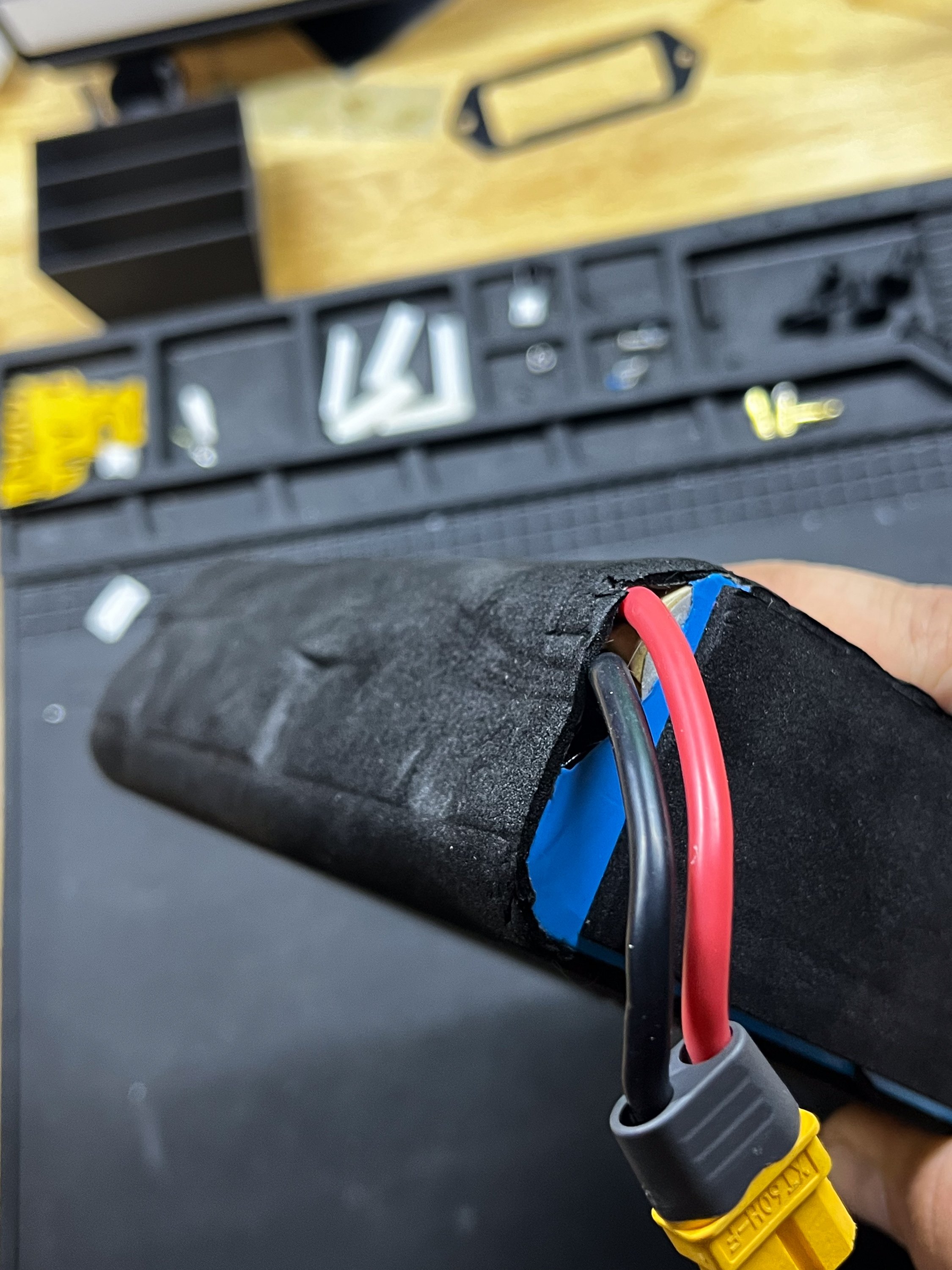


It doesn’t appear all that different from the pack inside a Onewheel XR, and the wiring connectors are also essentially the same. This includes the unfortunate reverse polarity wiring of the XT60 connector. However the coloration is still standard, with red being positive, and black being negative.


As shown above, there is a single overwrap of PVC heat shrink (not a dual crossing wrap), and a thin layer of foam around the pack on all sides, that also covers the non-wrapped portion. Below that foam, one can see the full wrap of fiberglass tape (or filament tape, or strapping tape as it may be called). This tape does a good amount of the structural work for the two halves of the battery, and there’s a good amount of it.


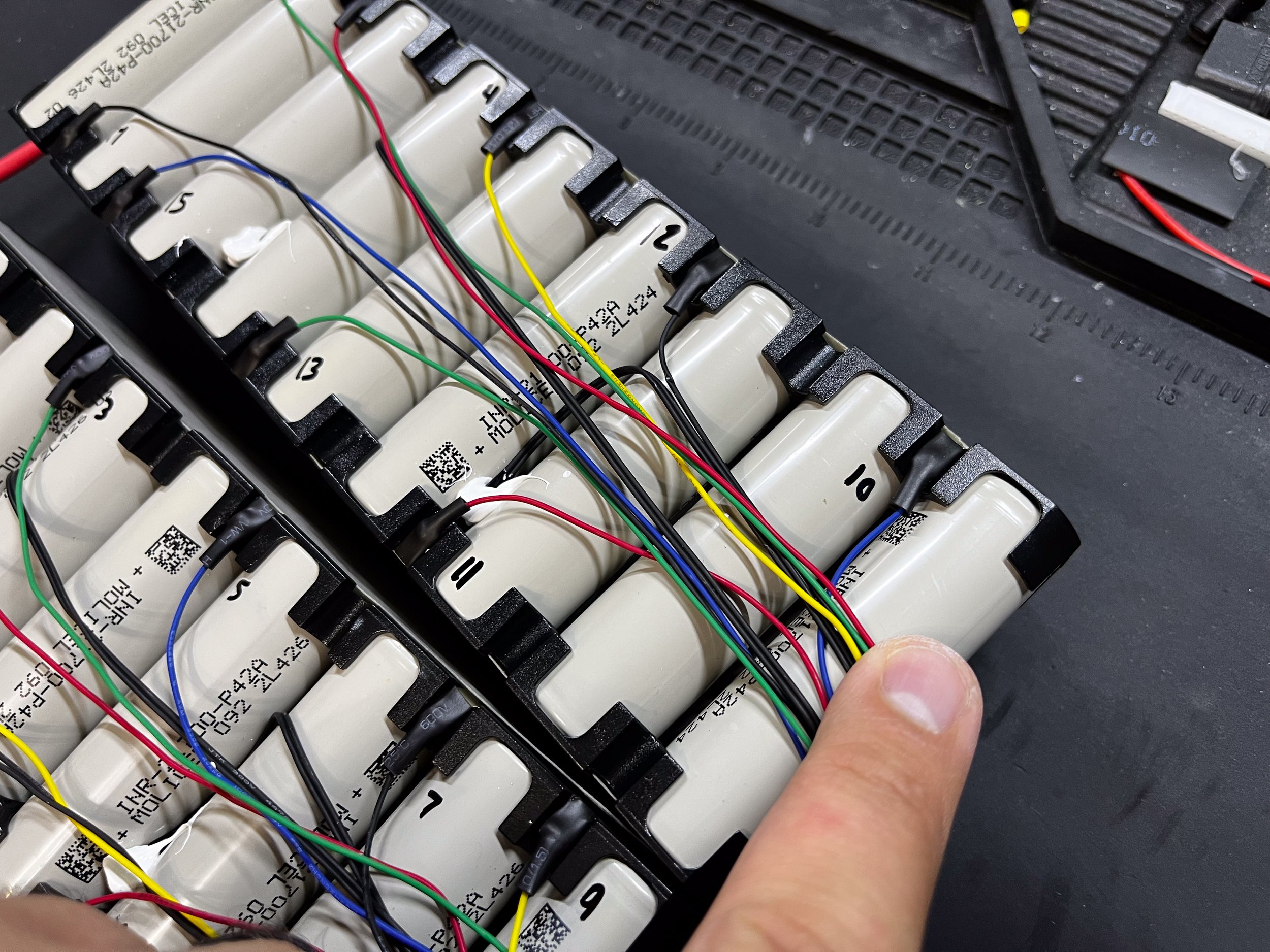
Below the fiber tape, similarly to an older XR battery, is the mess of balance wiring and temp sensor leads that lay across the cans of the cells. The wire itself, I’m unsure what kind it is. It’s likely not PTFE coated wire, as the insulation is fairly fragile and can be scraped away with a fingernail without THAT much effort, so I’m guessing it’s some kind of PVC coated wire, likely 26awg or 28awg, as it’s pretty thin. It’s thin enough that it all sits below the lips of the cell holder frame, and so there isn’t compression forces from the enclosure onto the wires and onto the faces of the cell cans. This essentially eliminates most of the pinching that would happen on the face of the battery. However, wire this thin and frail gives me pause, since the exit from the pack and the routing in the box depends on a design that entirely eliminates any stress or compression in order to avoid these tiny wires being damaged.
^This is made evident by the wiring durability issues present in the Pint X, for which I am currently writing a repair log illustrating the issues and fixes I have done in the shop. It may or may not have been published already.
Below are the balance wirings.


Regarding the temperature sensors, I’m still not 100% sure on what to think. Generally, thermistors (the commonly used type of temperature sensors) are fairly slow to respond to temperature changes. Combine that with the large difference between the internal temperature of the cell and the externally measured temperature at the outside of the cell wrap, and whenever I set up a battery with temperature sensors, I will make sure to set any temperature limits lower than is considered comfortable, to compensate for the thermal delay in th measurement.
That being said, air is a good thermal insulator, and so the more air around a temp sensor, the worse it will perform (from what I’ve tested and read from other battery professionals). This is why when I install thermistors, I will do my best to adhere them directly to the can of a cells, and use a thermal epoxy to bind it and encase it with as much contact area as is practical, as well as contact with the adjacent cell. The hope is to have the best possible contact situation to read pack temperatures.
Again, I’m not 100% sure this is worth the time, or if it’s just all surface level pageantry to appease those who want to know battery temperature either for peace of mind, or to be able to run a battery harder in their device without too much extra risk.
Either way, the application of the temperature sensors in this battery appear a bit lazy. A small bead of adhesive, and they aren’t actually even touching the cells for the most part.
It looks like they’re only going to monitor the ambient temperature alongside the cells, with an even further delay.


Looking around the battery, it appears to have the same (or similar) construction characteristics as their other batteries. The main terminals are generally reduced to a final nickel strip foldover, and the pack lead wire is soldered to that. Looking at the sizing of the nickel it does not seem suited to very high current draw, on account of it being sized at 0.15x10mm. The piece is short, so it’s not a long run of little material. However the ampacity of it is far far below that of the lead wire it’s soldered to, and can become one of the bottlenecks in terms of performance. In addition to that, the connecting matrix of nickel pieces are made with series connections of a similar 0.15x10mm sizing. It works, however this indicates that the power this battery is designed to supply is more on the moderate area of the spectrum for these kinds of devices.


This is the chart I use for reference regarding conductor ampacity. The chart is useful, and the forum thread has useful discussion and information on those numbers and their rationale.
https://forum.esk8.news/t/conductor-current-ratings-sro/7660?u=theboardgarage
Looking at the half way point, the series connection is similarly a singular 0.15x10mm nickel strip to jump the lower half to the higher half.


Moving on, I went ahead and numbered the balance wire spots, which have a couple of locations that take a bit of searching. The logic behind it makes sense, to keep balance tabs away from one another.


As shown above, once the balance wiring spots were labeled, I cut the heat shrink from the tabs and desoldered the wiring. The temperature sensors were also removed, which was fairly easy as they were barely adhered.
As mentioned above, the main terminal XT60 connector is wired in reverse. This is important to keep in mind when wiring the cable or harness for installation with a VESC, which is generally wired properly.
The XT60 was left alone, and the end builder can choose how to handle the reverse polarity XT60, as it’s generally easier to swap the direction of a wiring harness to suit the intended destination of the power connections.
Moving on to the new wiring, I elected here to use the same balance wiring harness I use for the custom packs I make for these DIY/VESC-based boards. It’s a JST-PH connector set, 13-pin and 12-pin, that suit the headers on the ENNOID XLITE V3. It uses 24awg PVC coated wire, which is thicker than the wire used in the stock harness.
Because of this, I don’t exactly know the level of compression that would result when the enclosure is screwed shut. It’s because of this, that I find it a good idea to get ahead of that by avoiding wire crossing when possible, as well as insulating the wires themselves from the cans of the cells. PVC in general isn’t the most compression-resistant insulation, and so rather than risk it, I prefer to hedge my bets in the more insulated direction whenever possible.
Similarly to the construction of the 18s2p ME4T and Power packs I made for DIY one wheel builds and conversions, I laid down a fish paper track along the side and the top of the pack, where the balance wires will sit.


Also, just to avoid having to redo it, I double checked the cell group locations with a meter, reading the addition of each 4v cell group with a meter.
While running the balance wires to their respective locations, I normally choose to bridge the unused wire spots for the XLITE inside the pack, so that way the battery can be connected to any XLITE V3, without having to bridge the pins on the BMS itself. Since the XLITE uses 2 12s ICs, each half of the pack goes to each connector. This means that the top wires of each connector need to be connected to the top of the last cell in the half. I just combine the balance leads to the top of that cell.
Sometimes it takes a bit of wiring creativity.


To suit the XLITE, I installed a pair of thermistors, the specs of which are located in the XLITE Pinout document on the XLITE V3 product page. They’re NTC 100kohm thermistors (bead type) with a beta value of 4250. These are the ones I use: https://www.digikey.com/en/products/detail/murata-electronics/NXRT15WF104FA1B040/3900396
Incidentally, Murata is the electronics company that bought Sony’s lithium ion cell division many years ago. So when seeing cell models like the VTC6, VTC5D, etc., those are made by Murata, not Sony. Just some bit of trivia.
Currently, I’m using the Omnifixo set for a “3rd hand” type of holder device. Previously I was using an aligator clip style, which worked fine. However the Omnifixo was recommended to me by the DIY eskate and drone communities, and using it has literally changed how I’m able to work. It’s brilliant, has streamlined my workflow for making wiring connections, and is one of the best tools I’ve purchased in a long time.
Some wires needed to be extended, but it’s mostly straightforward work at that point once the wire track is laid down on the fish paper and some dual sided adhesive.
The top half of the battery requires another run of wires from the other connector, and so to lay over that initial run, I have a track of fish paper going over it, and then the wires loop similarly up the edge and over the cells. I went ahead and combined the top-most wires into a single wire before reaching the 18th cell group tab. It was just easier to manage that given its location.


THE ENNOID REQUIRES AN XT30 CONNECTOR FOR ITS CONNECTION TO THE PACK TERMINALS.
Since the stock battery only has one XT60 connection (reversed) at its terminals, I also needed to install a small set of leads going into an XT30 connector, WIRED NORMALLY, to connect to the battery pack input on the XLITE V3.
Just like the lead length of the balance wires, I just placed a dummy XLITE (it’s broken so I just keep it at the bench for wire length fitting) where I assume it will sit, and then measure the wire length from there.
Then, it gets wired in parallel to the main terminal leads, as usual, with red to positive and black to negative, and the XT30 itself is wired with normal polarity.


It was probably superfluous, but I added a bit of fish paper under the positive leads as they passed over the other wires on the other half of the pack, since they may see some compression when the pack is installed.
Once everything was wired and placed, I checked the wiring of everything with a meter through the balance connector to verify that the cell groups were showing in the right place.
Then I connected the XLITE V3, ran through the basic configuration, and checked the information in VESC tool. I then connected a charge source to the charger input XT30 on the XLITE and verified the function.
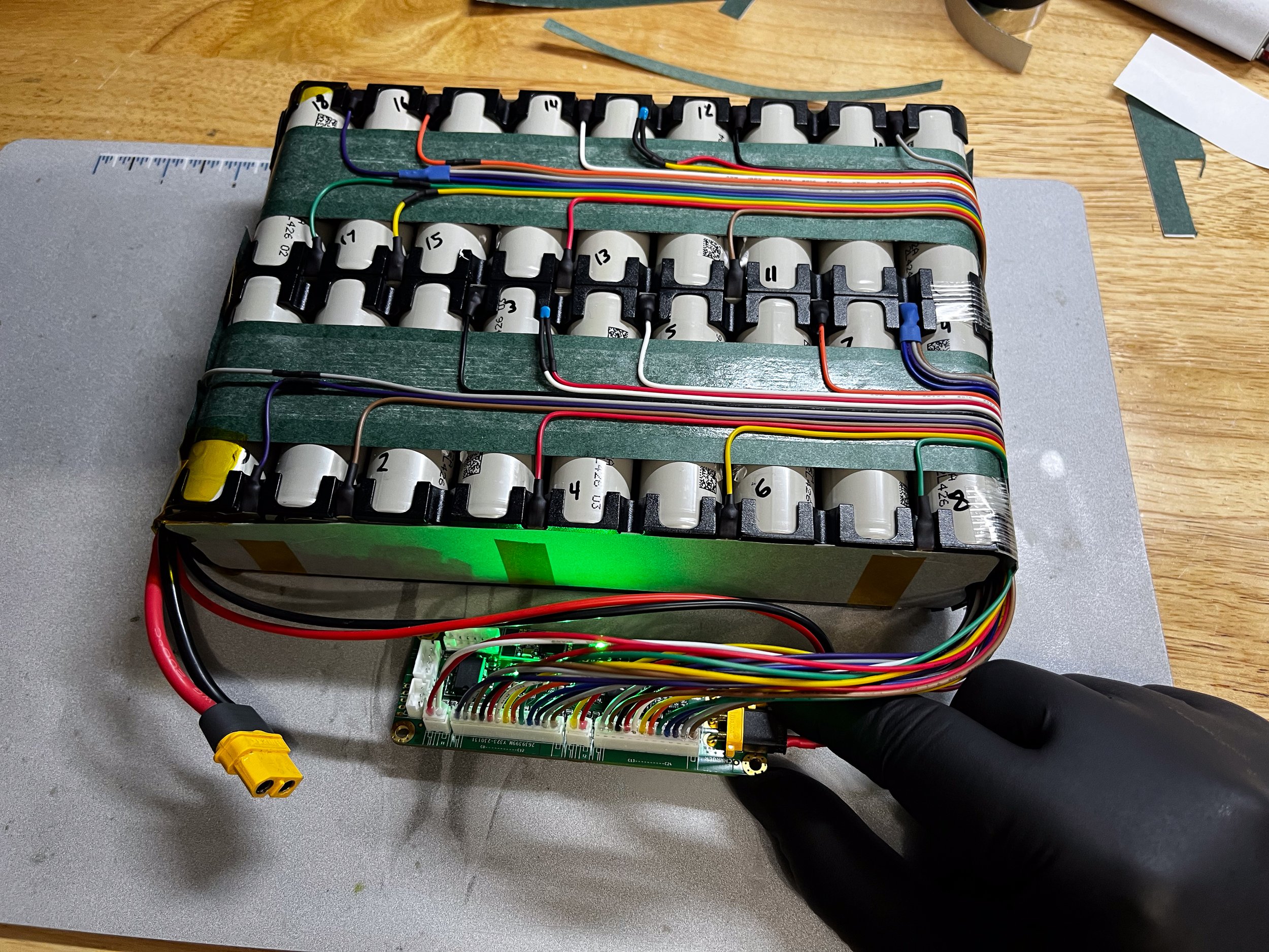


When everything looked kosher, and the temp sensors were responding, I secure the temp sensors with thermal epoxy (https://amzn.to/3p1RZQR) and allow that to cure.

Fiberglass strapping tape is reapplied (new, not reusing the old tape) to secure everything, and then a similar overwrap of PVC heat shrink is added and an appropriate label.


Some sheets of foam were included in the return shipment to be added during installation. I chose not to add it here myself, since I wasn’t doing the final install and so it seemed best to leave it to the tech installing the battery to choose where it would be appropriate to add the foam.