

VESC [DIY] One Wheel Lights | Arduino | Code by Mitch Lustig
Introduction
Code Repo by Mitch Lustig: https://github.com/Mitchlol/VESC_LED_UART/tree/float_package_buttons
If you’re a seasoned DIY builder, this kind of addition is probably not going to be that bad. If you’re a new DIY builder, then this project may not be for you. Some builds and projects are just a bit beyond the scope of a builder at their current skill level. That being said, it’s important to not be intimidated by this log article being really long and pretty wordy. With most things, I try really hard to make sure I get EVERYTHING out onto the page so that I don’t miss anything or leave any question unanswered. I find it helpful to explain the reasons why I do things in a build, and lay some foundation of understanding. This way, if the “why” is shown, the “what” makes more sense.
This is just a log of how I set up the LED lighting in my DIY VESC based one wheel board. The wiring is a bit involved, and it probably takes a bit of mental mapping out, but I will do my best to detail how it’s wired up, and why it’s done this way. This is of course, not the only way to do it, and there are already some pre-made PCBs that do one wheel lighting in some kind of way. So, if this is not something you’re interested looking into, then there are other options.
This was first worked out and put together at the end of summer in 2023, and it’s been slightly revised / smoothed out, and some things were learned as I ran into small issues here and there. I’ll do my best to lay those out as well.
Many thanks go to Mitch Lustig, who originally wrote the code for the Balance App in VESC Tool, before the Float Package was a thing. Back in VESC Firmware 5, the Balance Package was how VESC could be used to run a balance vehicle like an EUC (which I think was the original intent of it). Similarly, Mitch wrote his code for an accompanying accessories setup called Balance Buddy, which would use an Arduino to run LEDs, a small screen, and a buzzer, to provide riding feedback and telemetry.
As the VESC based one wheel area grew, the desire for LEDs that functioned somewhat like they would on a Future Motion Onewheel also grew. I had tried for a bit to get the rESCue units to work (another VESC compatible lighting and buzzer module found at https://rescue.company.site/products/rESCue-c117821761) but it and I were not having much luck and so I went looking for other options.
After some brief conversation with Mitch, and a few revisions, the code that is available on Mitch’s Github became a thing, meant to run on an Arduino Nano and power either RGB or RGBW LED strips.
What Is It, and What Does It Do?
This particular setup contains an Arduino Nano microcontroller, a voltage converter, a pair of LED strips, and the wiring in order to connect it all to make it work. It reads the data from a VESC from its UART port, and uses that data to change the LED colors and show the battery level on those LEDs.
In use, it looks something like this:
You may notice that the colors of the LEDs change directions along with the board. This was, in my opinion, the main desired function of lighting on this type of board, and so I was glad to just have that. However, Mitch was able and willing to put his own spin on things, and what resulted was code that not only switched directions based on motor direction, but was also responsive to the foot sensor (it brightens when you step on it, and can be configured from the foot sensor) and when the board is idle, it will fade into a battery meter.
Warnings & Precautions
While this setup has shown to work well and be fairly robust, there are absolutely things that I have found are worth being aware of. Please take note of these.
This may be easy fare for a seasoned DIY builder or electrical engineer. However, it is NOT at all an easy DIY project for anyone who has little to no experience soldering, wiring, and working with electronics. THIS IS NOT A FIRST DIY PROJECT. While the process is straightforward to many, for those who can’t even change the plug on their charger, this is not someting to dive head first into. I’m sorry if that is a bit insensitive, but some of these parts are not cheap, and if done incorrectly, you run the risk of damaging other components on your board.
The buck converter that was used here is meant to be an isolated power supply. This setup requires that it be de-isolated. This is done through bridging the input and output grounds. The reasoning will be explained in the “Grounding” section.
The buck converter used here is a very high quality one, meant for railway use, and the data sheets cite a 6mA idle/off current draw. This is a bit higher than I would normally like, HOWEVER, in practice, I have not measured any of them to actually draw that much. The ones that I have measured draw between 0.5mA-3mA, and that is something I am personally comfortable with.
IF YOU ARE GOING TO DO A SIMILAR PROJECT, YOU NEED TO BE AWARE OF IDLE CURRENT DRAW IF YOU EVER LEAVE YOUR BOARD IN STORAGE FOR LONG PERIODS OF TIMEThis setup was done on my board while it was being constructed. I tested it on the bench, and so the wiring was done when the battery WAS NOT CONNECTED.
IF THIS WERE TO BE ADDED ONTO AN EXISTING ACTIVE/ENERGIZED WIRING SETUP, IT SHOULD BE DISCONNECTED FROM POWER IN ORDER TO SOLDER TO THE MAIN POWER CONNECTOR GOING TO THE VESC.
Grounding
Again, I have to credit this part to Mitch, as he mentioned the grounds needed to be bridged for this setup to work. Below I’ll explain the reasoning for that.
In the Parts Used section, there’s a photo of the pin side of the buck converter being used, and it shows a green wire going from one set of black wires to another set of wires. This is to bridge the ground from the input to the output. The buck converter is an isolated power supply, where the output of the power supply (in this case, “power supply” is used interchangably with “buck converter”) is electrically separate from the input. Generally, this keeps things like spikes from damaging more sensitive electronics. Since the input power source could be up to 160v, and the elecronics on the output side are at 5v, it would be a problem if issues at the source ended up frying the electronics being powered.
Anyway, the issue here is that the power coming from the buck converter is going to power the LEDs, which is why this project needs a buck converter to begin with. The VESC itself cannot power the LEDs, as they will draw about 1.5 amps, and the 5v power supply on the VESC itself can’t handle that. The VESC’s 5v power is what powers the logic stage and everything else on the VESC, and if that fails or is overpowered, the device will fail and the rider will be injured.
Since the LEDs are being powered by the buck, but the LEDs are being controlled by the Arduino Nano and the Arduino Nano is reading the data from the VESC, they all need the same ground reference in order to work.
Data and voltage all work off of a reference point, a common ground. In a battery powered device, this common ground is USUALLY the negative-most point, which is USUALLY the negative terminal of the battery.
If you take your multimeter and set it to continuity check mode, you will find that all of the ground pins on a VESC are connected to the negative bullet connector of it’s power input. All voltages and data are referenced against that ground. And in this LED setup, that has to remain the case. The Arduino Nano is connected to the UART port of the VESC, and so it is getting its 5v, ground, and the RX/TX signal from the VESC, all referenced against the same common ground.
The LEDs get their data signal from that Arduino, referenced to the battery negative, and so the power from the buck that is powering them, has to be referenced against that exact same ground. If it’s not, then there will be issues. I have experienced these issues, and I may or may not have damaged a VESC in doing so.
For these reasons, the buck converter has to share the common ground back to the battery negative. This is why the grounds are bridged on the buck converter, as shown below.
Fortunately, this does not appear to have any impact on the switching function of the RC/enable pin (since it operates on a high/low logic referencing the ground) or idle current. They appear to be the same.
YOUR MILEAGE MAY VARY DEPENDING ON THE BUCK CONVERTER YOU END UP SOURCING.
Parts Used

Most of the parts that were used for this are fairly straightforward. This log is just going to detail the specifics of the wiring setup. As far as how the LEDs would be mounted, those largely depended on what kind of front and rear enclosure box I used, since they have different ways of mounting LED strips. I covered some of that in a previous project log, and that can be seen here:
https://theboardgarage.com/articles/18s2p-vesc-one-wheel-build-w-hypercore-the-red-pill-aka-the-kev-special-a-project-log
LED Strips:
https://amzn.to/3Ox01KV
^These thin strips work, but so will NeoPixels as they work off of the same logic and libraries.
NeoPixel Sticks:
https://www.adafruit.com/product/2869
Arduino Nano:
https://amzn.to/4bqpi34
(These work well. I have tried the Arduino Nano Every, and it did NOT work at all for some reason, so I just went back to these.)
Resistors (10k ohm, 220 ohm, 500ohm)
https://amzn.to/4957WHB
https://amzn.to/48RblK1
https://amzn.to/3OvWvQT
3-Core Cable:
https://amzn.to/3SM3pny
PC Clear Epoxy:
https://amzn.to/3UtME22
DC to DC Buck Converter:
Alright…so this is a bit complicated. I will first show the exact buck converter I used, and then show an alternative since the one I used is a bit hard to find.
Meanwell RSDW10H-05:
https://www.meanwell-web.com/en-gb/dc-dc-railway-single-output-converter-input-43-rsdw10h--05
https://www.mouser.com/ProductDetail/MEAN-WELL/RSDW10H-05?qs=55YtniHzbhDJ47d93l%2FwCQ%3D%3D
https://www.digikey.com/en/products/detail/mean-well-usa-inc/RSDW10H-05/11482320
^These, as I said, are hard to find. I usually find them by calling more local electronics supply companies and seeing what they have on order, and will order from there. As linked above, they can be found at the usual online electronics vendors, but they’re on backorder a lot of the time and are usually bought up quickly.
Below is an available alternative that others have used successfully in this way so far, and it’s the same spec converter by a different company:
https://www.mouser.com/ProductDetail/TRACO-Power/TEN-10-11011WIRH?qs=A6eO%252BMLsxmTUGaFiafDybw%3D%3D
If that link shows that it’s sold out, then that model may be available elsewhere.
I’ve noticed that sometimes in a hobby, when certain people get a whiff of a possibly popular project, they will buy up all the available stock of something in case it can prove lucrative. This can be kind of crappy for single DIY builders who want to just do a project, but that’s kind of the reality of the world and especially this hobby.
People will be people.
And so, because of that, I am adding the following information that may help a DIY builder source a compatible part.
It was first the Discord user Maclak (of AV Wheel enclosures) who showed me the larger 8 amp version of the Meanwheel buck converter, and I was interested in that because it worked up to a high voltage, and contained an enable pin (an onboard on/off switch, which is pretty important). I looked up the model number, and combed through the Meanwell product catalog for railway power supplies (which this thing is), and found a smaller 2 amp model. That’s what I linked above. It outputs 5 volts at 2 amps (or 2 amps at 5 volts), which was perfect for my needs.
Naturally, it was already difficult to find, which is what led me to searching online and cold calling electronics suppliers. Eventually, I found a few in stock in the Northeast, and picked those up.


These items are meant to be designed into a PCB, and they have little through-hole legs for that purpose. However, they work fine by just soldering to those legs and wiring it up that way. And their metal casings make for easy mounting into an enclosure.
I’m sure folks will or have already taken such units and made PCBs for/with them. The one on the right that I ended up using is a DIP24 sized package, and so is the Traco Power unit I linked above. The one on the left is clearly larger.
The DIP24 sized package seems to have in it, a few different power supplies / buck converters available. The Meanwell are likely popular and hard to find because Meanwell is a known reliable brand for power supplies (you may be familiar with the brand from PC or 3D printer power supplies).
However, there are some notable specs that one could look for in sourcing such a buck converter that may help.
PLEASE NOTE THAT THESE SPECS DO NOT GUARANTEE COMPATIBILITY. A BUILDER IS RESPONSIBLE FOR THEIR OWN TESTING, AND HAVING SPARES OF THINGS THEY MAY BREAK/DAMAGE WHILE TESTING.
5 volt or 5.1 volt output. This is the voltage used for the RGBW SK6812 LEDs, and powers the Arduino Nano.
2 amp current. Or, if you need more, then whatever it is the project needs.
Wide voltage range. In the case of these converters, it’s about 40v up to 160v. That’s well above the 75v or 84v a VESC one wheel project (or most eskates) are likely to operate on.
Enable/RC pin. This is the onboard on/off switch. Also called a remote on/off. It depends on the brand and model, but it will be a single pin. It should be described in the data sheet.
Here is a filtered list of power supplies / converters on Mouser that meet these criteria, and so in the absense of the above linked parts, it may be worth combing through the list and seeing if something may help:
https://www.mouser.com/c/power/dc-dc-converters/isolated-dc-dc-converters/isolated-dc-dc-converters-through-hole/?input%20voltage%2C%20max=121%20V~~160%20V&number%20of%20outputs=1%20Output&output%20voltage-channel%201=5.1%20V&rp=power%2Fdc-dc-converters%2Fisolated-dc-dc-converters%2Fisolated-dc-dc-converters-through-hole%7C~Input%20Voltage%2C%20Max
The Wiring Harness


The wiring harness / cable I use is the Floatboxx cable, and either the older 12-core or the newer 14-core version (a collaboration between The Board Garage and Floatboxx) will work. Or, if a cable/harness assembly is being made, then the needed wires can be added.
By the time you may be reading this, I may have already added more stock of the cable to my web shop. Please check there. If not, I will also link the Floatboxx site. I’m currently working on getting some stock of all the Floatboxx items in the store for domestic builders.
https://theboardgarage.com/store
https://www.floatboxx.com/shop
In the cable or harness itself, what is needed is 3 wires for the 5v, ground, and data connections to get to the rear enclosure box for the tail light.
Shown above are examples that were made. Note in the first picture, that the main discharge connector (XT60) has a pair of wires that are split off. These provide the battery power to the buck converter inputs. In this case, I used a JST-SYP connector, since I had them laying around from old Meepo board repairs. You can find them here: https://amzn.to/493uLvs
They happen to make for a decently easy disconnect in the event that I need to store the board for a long time. I can open the lid to the enclosure, disconnect that, tape it off if needed, and the buck converter is disconnected entirely.
Note also in the first picture, the left most connector is the 3 pin JST that’s meant to take the 5v, ground, and data mentioned above, to the rear. The last picture shows those wires headed to the tail light, also connected with a male and female JST connector.
Those can be done a couple of ways. Above are done with the male header of the JST, which can be found in any JST kit. But another kit can be found with the make crimp pin version of the JST-PH connector. I’ll link some below:
https://amzn.to/3OrwTok
https://amzn.to/4bidIY1
Headlight
It’s really crucial to bench test everything before committing to adhesives and installations. The way I did these below, is permanent. And so if a part of the LED was defective, I’d want to find out before I couldn’t fix it
The LED strips linked above are what were used in the photos shown in this log, as well as the earlier published build log of that board. I did do another build, where the headlight was made of Adafruit NeoPixel Sticks, and those were joined together and installed into a 3D printed Fungineers box.
The Floatboxx enclosure uses a separate housing for the headlight, and that has to be 3D printed. I printed it from Polymaker PolyMax PC (polycarbonate). There are 2 files available. One is the original file that’s meant for an LED strip shaped like a NeoPixel. There is also another housing that was done as a remix by Eric Ugland, which can be found here:
https://www.printables.com/model/511192-floatboxx-led-holder-sk6812/files
^This is the one I used for this setup, along with the LED strips linked above.
As a note, Eric Ugland offers a lighting unit that uses the WLED software: https://www.ugland.camera/vesc
I chose not to use that particular item, as I wanted the lights to be controlled directionally, and so having them interact with the VESC was necessary.
Shown below are the headlights mentioned, in the printed holder for the Floatboxx, and the Fungineers front box print.
In either case, the wires are terminated with a 3-pin JST. Here, it’s a male header that was adapted. This was done after the wires were threaded into the enclosure.


The first 2 photos show the Floatboxx setup. Note that I used a rubber grommet rather than a cable gland. It’s a very tight fit, and I’ll link the wiring and grommets below. In the rest of the photos, are the front LED strips for the Fungineers print, which are the Adafruit NeoPixel Sticks. Since they run on the same libraries, they both work the same. Note that these are both the 5v RGBW variety. They have the extra dedicated white channel on the LED.
On these, I did not install what most would consider a “window”. Instead, they were potted in a clear epoxy (linked below). This sealed them entirely in, and took care of possible window seal leaks. For the Floatboxx holder, I stripped the cable back and used heat shrink to create a single surface into the holder, and the epoxy was flowed into the entire holder. Afterward, I added a bit more into the end opening after the main part was cured.
For the Fungineers box, I did similarly, but I did add a hole on the other side for the sake of having the NeoPixels oriented the correct way to show through the bumper cutout. I used some hot glue to dam up the holes before pouring the epoxy. The epoxy potting also helps act as a heat sink for the headlight, since it runs on full bright with all channels. For the NeopPixels in the Fungineers box, I set their position where I needed it, and then epoxied them to the area to make sure they stayed aligned. After that, I potted the whole area.
For mounting the holder to the Floatboxx, I drilled the holes out a bit, and used M2.5 heat set inserts, and M2.5 button screws, along with a 1/4’ strip of clear VHB to further secure it to the metal flange of the box.


Taillight
In this case, I used a Badger/TFL Torque Box. It’s a clear injection molded polycarbonate enclosure for the battery. I make 2 batteries that fit this:
https://theboardgarage.com/store/p/18s2p-50s-cells-custom-battery-for-vesc-onewheel-builds-conversions
https://theboardgarage.com/store/p/18s2p-power-p45b-pack-custom-battery-for-vesc-onewheel-builds-conversions
This month, I will also be releasing the 20s2p 21700 Split Pack, and the rear pack of that setup will also fit the TORque Box.
Since the TORque Box is clear, not a lot has to happen for the taillight. I’ll show the photos of how I installed my taillight. I needed to line up the LED strip a bit left-ward (looking from tail to nose), so that it would all sit and clear the window of the Badger TORque Bumper. With this 144-LED strip, placing it in that spot will show which of the plastic wings/nubs need to be trimmed off. Some on the left will sit in between the LEDs, and the rest will conflict.
After that, the tail light was wired up and tested, and once shown to work, it was secured in place with a few small globs of the clear epoxy. It’s not an ideal solution, but it does work, and isn’t impossible to remove if the tail light malfunctions. So far though, it hasn’t shown to be problematic, so I don’t expect the taillight to randomly fail.


Originally, I had some concerns about heat at the taillight. However after a good amount of bench testing, the taillight going at a single color does not seem to generate much heat at all. If the LED strip is run at full white, with all channels on, then it will generate heat. However this should be set as a single color, like red, green, yellow, etc. and not full white.
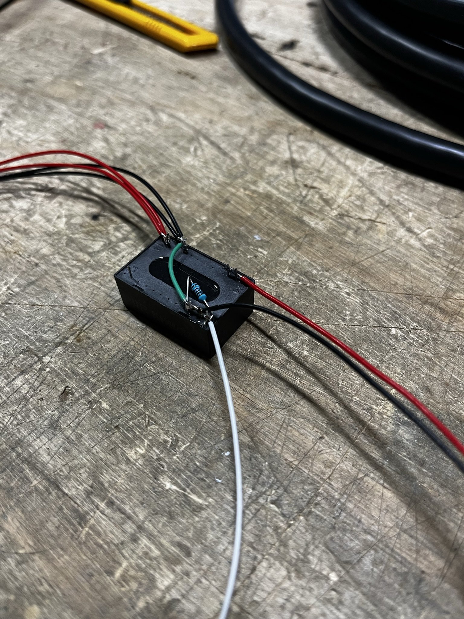
Buck Converter
The wiring for the buck converter was done in a few steps, and so I’ll just outline what I had to do, and then show the photos of what it looks like.
Add the power input wires to the input pins, with the mating JST-SYP connector that comes from the wiring harness.
Bridge the enable/RC pin to ground through a 10k resistor. This pin if left alone (floating), does nothing. The converter is just on. If it’s brought low (1.2v or less), that turns the output off. If it’s brought high (~3.1v or higher) that will switch it on. So, the 10k resistor allows this to be connected to a pin from the VESC (I’ll use the 3.3v pin) to switch it on. And when that 3.3v goes away (the VESC turns off), it will drain through the resistor to ground, and turn the buck converter off. The resistor keeps the 3.3v from shorting to ground, which would be bad. And so, the 10k resistor sits between the enable/RC pin and ground, and this makes it function.
Bridge the output ground/negative pin to the input ground/negative pin (explained above in the Grounding section).
Add a pair of wires to the output positive and output negative. These will be going to the LED strips to power them, and so I terminated these in regular JST-PH crimps.
The pins are longer than they need to be for THIS kind of use, but I generally left it all alone until after it was tested and checked. Once it was known to work, I trimmed the extra lengths off and added some hot melt around the pins to secure the wires, relieve strain, and keep the close pins and wires isolated.
Arduino Nano
As mentioned in the parts list, I tried the Arduino Nano Every, and I could not get it to work. I don’t know why. So this is the Elegoo make of the Nano, and so far it’s shown to be pretty reliable. As usual, your mileage may vary.
For this part, I soldered 6 wires in total: The 4 for the UART port (RX, TX, 5v, Ground), and then 2 for the LED strip data pins. Those went to pins 10 and 11.
The 5v wire went to the 5v pin on the Nano, and not the Vin pin. The Vin pin is meant for 7-12v unregulated power, and it goes through the Arduino’s power regulator. From that, there’s a voltage drop as it keep a steady 5v supply to the PCB. In this case, the 5v power is being supplied by the VESC directly, and that power supply is regulated and stable. So it will go directly to the 5v power pin (which is where USB power would go anyway), and I also connect the ground.
https://forum.arduino.cc/t/is-5v-voltage-too-low-to-power-arudino-via-vin-pin/850345/2
Please remember that these get swapped at the VESC UART port. RX is the receiver, and TX is the transceiver. RX gets data, TX sends data. AND SO, they need to go to the opposite pin on the VESC. The RX on the Arduino goes to the TX on the VESC. The TX on the Arduino goes to the RX on the VESC.
These 4 wires will go to the 7-pin JST that is needed for the UART port on the Little FOCer VESC. There are pin out diagrams available by searching, as well as on MakersPEV.com, and in a prior article here for a VESC DIY one wheel build.
That UART port also has a 3.3v pin, and that will be taken by the white enable/RC pin wire from the buck converter. So this wiring setup will take just one JST port on the VESC.
Below you’ll probably see different wire colors from the Nano. Just ignore those, and use whichever color coding you’re used to. The above image had different 5v/ground wire color, but red and black are most common and easy to see. I usually use yellow and green to TX/RX, and so that’s worth noting here.


LED Data Pins
Pins D10 and D11 on the Arduino are used for the LED data. For these, I usually use a green wire, as it’s easy to visualize. The 3-core cable I linked above doesn’t have that, so I just match it to the yellow wire there.
So long as you can trace the wires to where they need to go, it’ll map out properly.
Apart from that, I have found that these data lines benefit from pull-up resistors. That’s just a low value resistor on the data line itself, that helps to eliminate noise. I’ve tried several different values, and arrived at these that seem to work properly:
Headlight resistor: 330-500 Ohms.
Taillight resistor: 220 Ohms.
When I first set this up, both Mitch and I ran into flickering at the taillight, and adding the pull-up resistor seemed to fix it. I originally had higher resistance values, but in some occassions would run into more flickering of different types. When using the Floatboxx cable wires, it seems that these values work properly and eliminate flickering at the rear. As usual, your milage may vary.
Here is some reading on that topic:
https://learn.adafruit.com/adafruit-neopixel-uberguide/best-practices
https://electronics.stackexchange.com/questions/177019/why-does-a-resistor-in-my-neopixel-data-line-work-at-all
https://forums.adafruit.com/viewtopic.php?p=796512
I heat shrinked them in different colors to visualize which data wire was which. These were also terminated in a regular JST-PH crimp, and would meet the others from the buck converter in a female JST-PH connector.
Flashing The Arduino Code
To flash sketches (the code that gets written to Ardunio boards) onto the Nano, you will need to install the Arduino IDE:
https://www.arduino.cc/en/software
You will also probably need a Mini USB cable, since the Nano uses that older style port.
https://amzn.to/3us9wEf
Having these, you will need to find the code on Mitch’s Github page:
https://github.com/Mitchlol/VESC_LED_UART/tree/float_package_buttons
If all that is sorted, here is how I flash the code to the Nano.
Connecting Things Together
It’s at this point that I would actually do bench testing of the LED strips, the buck converter and the Arduino altogether. Beforehand, I would likely have checked the buck converter with a meter and a power source to make sure that it’s outputting the 5 volts I need and turning off how I need.
This kind of testing is why it’s easier for this to happen during a project build process. But, if it’s added on later, then bench testing the parts is still a good idea.
That being said, it’s mostly a matter of knowing where the wires need to go, and why. As shown above, the Arduino wires mostly go to the UART port, for the data and power.
The two data pins from the Ardunio will go to the center JST pin on the 3-pin connector that’s going to be plugging into the headlight and the harness wiring to the rear box for the taillight.
The enable/RC pin from the buck converter, I personally added it to the UART port, since the 3.3v pin was enough to bring that pin high and turn the buck on. I have read some buck converters have an enable pin that need more than 3.3v for it to register as “high”, so you may need to use an open 5v pin on the VESC for that. Please check data sheets and test before doing any permanent assembly.


Bench Test
Please note that this software is meant to read the information from the Float Package. It will still turn on and function without that, but it won’t be able to be configured or read the battery level without Float Package being installed. Since this is being tested before the board itself is configured, I installed Float Package to test the lights, and then uninstalled it before setting up the whole board. I could also have just disabled Float Package after testing lights, but either way, it’s needed for the lights.
If things weren’t screwed up, then everything should be able to be connected together, and it should just light up the LED strips when power is connected and the VESC is turned on.
If Float Package is installed and things are working, pressing the foot sensor SHOULD activate the lights to full brightness after they have faded to the idle dimming part. If it doesn’t respond, then something is off. Maybe the footpad connector is not connected to the VESC, or something wasn’t connected properly, or the code wasn’t flashed, etc.
There has been 1 specific sample of a Little FOCer v3.1 that for some reason, WOULD NOT work with the Arduino. I have no idea why. The UART port worked normally with an external bluetooth module, and appeared to function fine. But for some reason, it just would not communicate with the Arduino. I just swapped it out. Maybe I damaged something, I honestly don’t know and couldn’t figure it out.
Lighting Configuration
The first time this code runs, it isn’t set up to the length of LED strip or specs of this board, and so it has to be configured. This is done through the foot sensor pads, and there is a menu system for each option. The first time it boots up, only about 7 LEDs on each strip would be lit, and the battery meter may not be set as needed. The default LED type is RGBW, and since that’s what’s being used here, that will not need to be adjusted.
I found it helpful to just go through the configuration while everything is on the bench, to make sure I could configure it correctly. To do so, the “nose” of the board has to be pointed upward. If the VESC IMU has not been calibrated yet, then you will have to just go into VESC tool and look at the RT Data tab, and move the VESC so that it appears to be “nose up” as far as the VESC knows.
In my case, that was with the Floatboxx up on the side. I put some tape on some exposed pins of the parts so nothing would short circuit anywhere or do anything damaging while I moved the boxes. And I had the footpad connected.


It’s now that a single zone press on the sensor will enter the configuration menu. The menu options are shown by the number of LEDs lit, and pressing and holding both zones of the sensor will enter the option menu and scroll through the options.
I will include video clips of how I configured the lights for my specific case, but it’s important to know that the menu items that need high number inputs (cell count for battery, LED count for the LED strip) will need to cycle through groups of 5. Kind of like making tally marks, where you make groups of 5 and then start a new one. So, 18 cells for an 18s battery would be 5 + 5 + 5 + 3. You would hold both zones of the sensor until you counted that, and then release to set it. I will demonstrate that below.