Pint X Battery Repair - Balance Wires & Broken Solder Joint
Please note, that even after repairs are made to such a battery, the enclosure may need to be modified to prevent similar damage from happening again. These are repairs, not protective measures against the same issue. Those need to be implemented in the enclosure itself, which seems to be the cause of these kinds of damage.
Please also note, that this is not a service I can currently offer openly at the shop. This is why I am logging this job as thoroughly as I can. My hope is that other qualified and competent techs and repairpersons will be able to help local customers with such kinds of repairs.
Recently I took another pro-bono repair job, so that I could do some research and documentation on a common issue that I have seen with the Onewheel Pint X board. The long and short of the issue is that due to the placement of the balance wiring in the enclosure, and the adjacent dividers, the wires are installed under pressure and they become damaged over time. Since the wires are pressed together and their insulation is worn away from the abrasive surfaces of the dividers, there is the potential for short circuits amongst the wires, leading to battery errors and further damage.
The scope of repairs provided by the manufacturer vary, naturally, and so some may feel it preferable to either repair it themselves or have a local/independent tech/shop perform the repair.
THIS IS NOT A GUIDE, ONLY A LOG OF ONE JOB I COMPLETED IN MY SHOP.
Given the scope of the damage in this particular battery, it’s possible that these repairs are representative of some other cases, however since I have only documented one repair, I cannot say for certain that all the repairs done in this job can be universally applied to all issues experienced with this battery. It is up to the individual tech/repairperson to assess what methods apply to the damage needing repair.
Scope Of The Damage
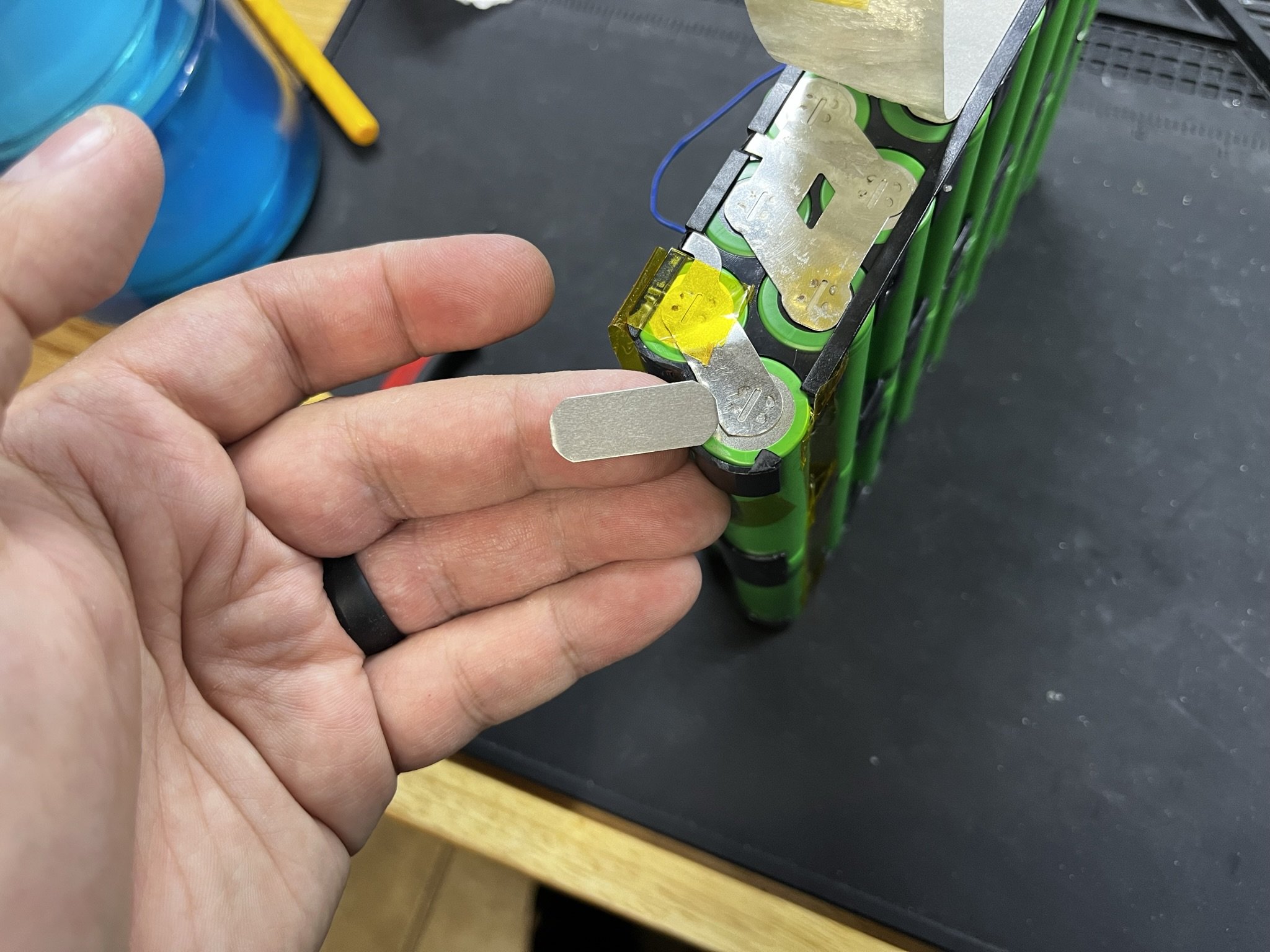
Below are photos showing the damage that was present on the battery. From the information I was given, the balance wires became damaged during use, and the main negative lead (wire) incurred a fracture at the solder joint. Both of these issues were attempted to be fixed by the owner, without complete success. I have seen cold solder joints on the Pint X batteries before, so this is not an isolated issue on this wiring, however in this case, it seems that either the joint breakage or the attempt at repair, further broke the nickel tab. It would have to be cut and replaced.


Opening The Battery
Most Future Motion Onewheel batteries are designed and built fairly similarly. This can be seen by the photos in this log, as well as those in a prior log showing a Onewheel GT battery.
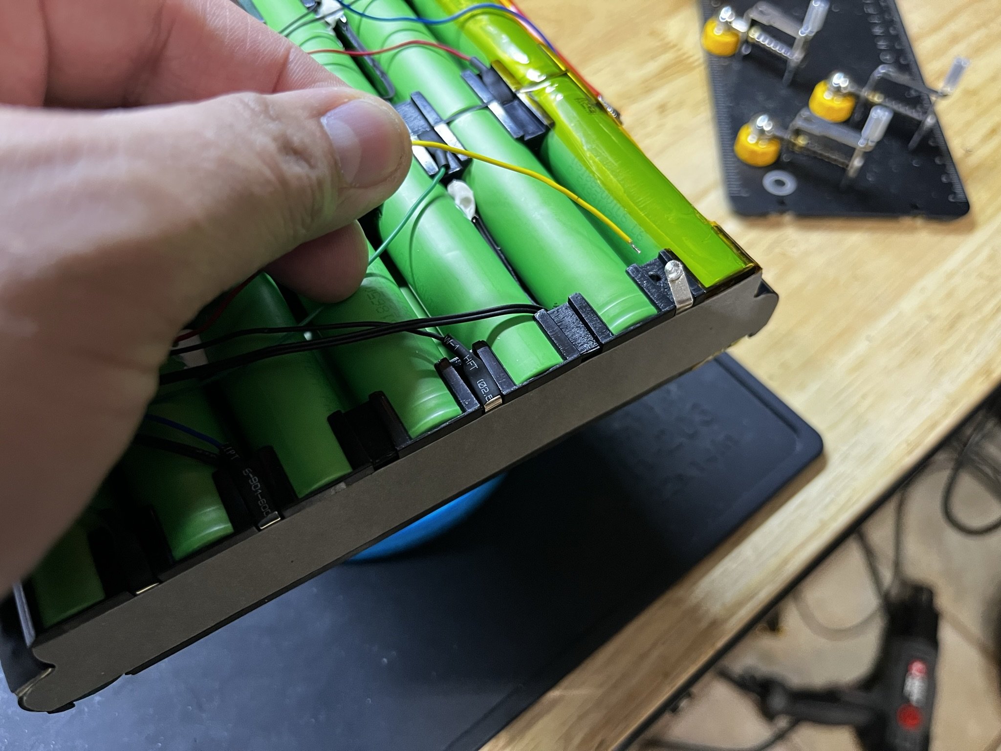
After removing the shrink wrap and foam, there is a layer of fiber strapping tape. Below that, is the meat of the battery, which is the cells in the frame, the wiring, and the insulation bits.


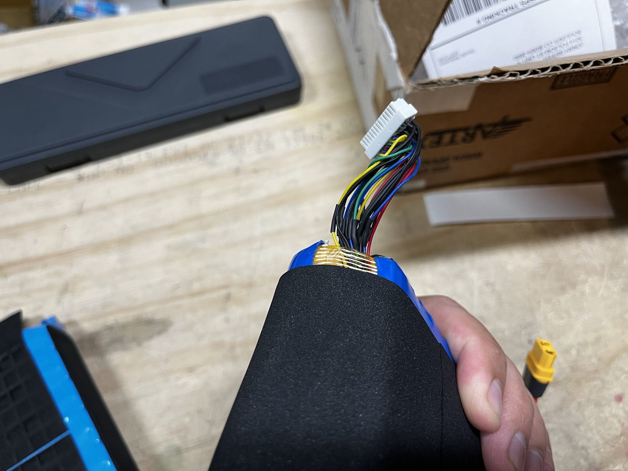
When opening the battery, there are a couple of things found that are a bit unfortunate. Firstly, is that the balance wiring and temperature sensor wiring all run on the underside of the pack. Normally, I’ve seen it run on the top of the pack.
Even though the batteries all get installed in what can be called a “compression fit” (this is where padding and enclosure size lead to a slight squeeze on installation, in order to prevent any internal parts from moving during use), the placement of the wiring underneath the pack seems to have led to more wire pinching than I have seen on other batteries of this style (from the GT and XR).
Following from that, there does seem to be a presence of wires being squished and pinched against the cans of the cells. They don’t look damaged entirely yet, however it does show areas where the longer a device is used, the more likely it becomes that the wires will have their insulation worn down.
Lastly, one can see the presence of red liquid electrical tape from the prior attempt at repair. This is a common way that end users try to prevent further damage, however given the nature of liquid electrical tapes and the nature of these causes of damage, it’s not really a sustainable option. Liquid tapes are very soft, and require multiple applications to achieve any kind of thickness of the coat. In these cases, the existing insulation has been worn down by harsh edges and pressure, and so there is an incompatibility between these things.
Repairing The Main Leads
The main leads on the XT60 seemed like they would benefit from a replacement. So a new part was made, and wired in reverse as per the stock XT60 connector. Lead lengths were approximated from what was originally there.


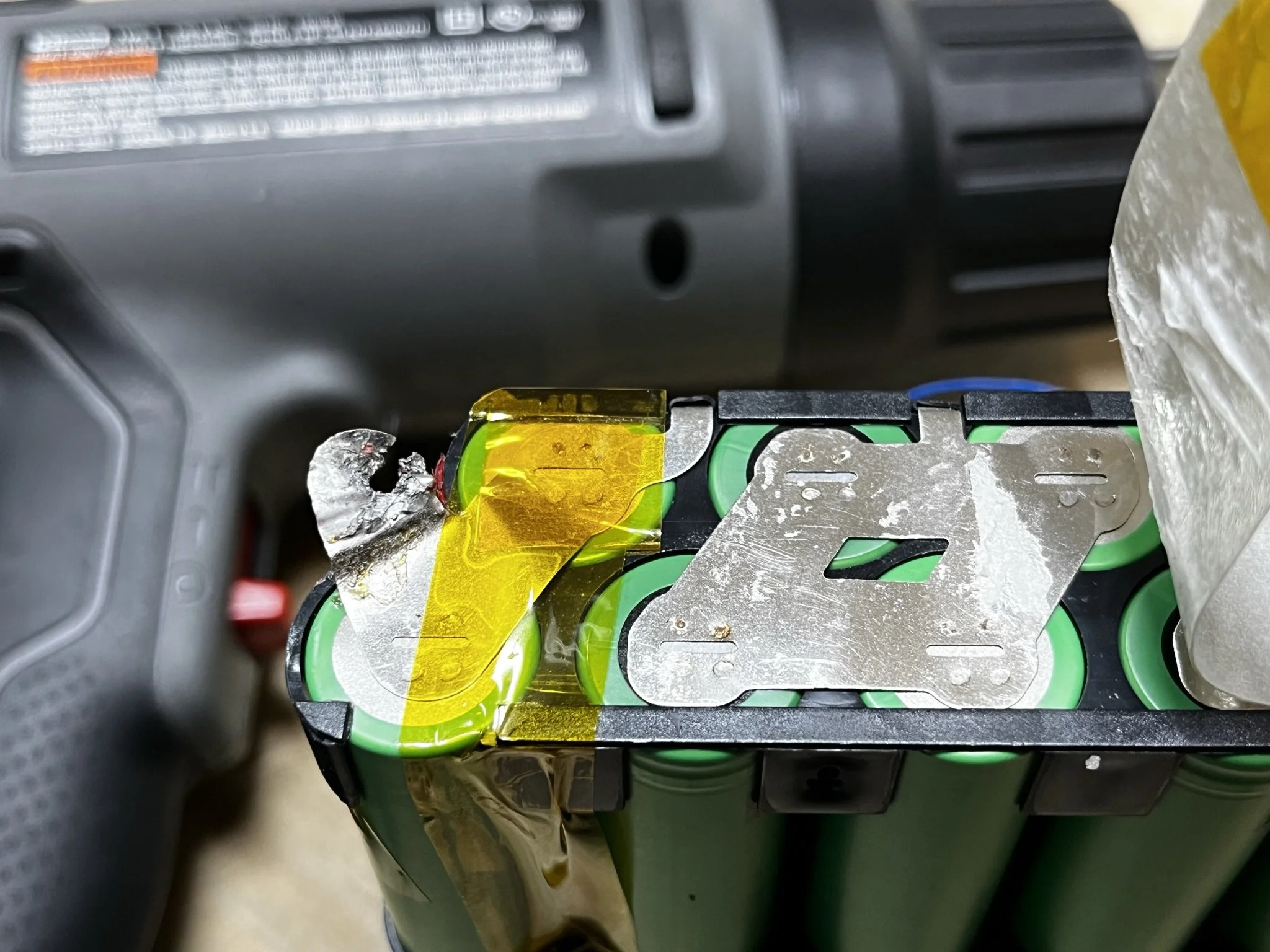


The nickel tab connecting the main negative lead was also cut, and a new piece cut from nickel stock (slightly thicker, as this is what I had that was closest). The new piece was welded to the same negative terminal of the pack, and the leads were resoldered to their original positions. The piece I used was a 10x0.2mm pure nickel strip cut to size, and the corners rounded off and sanded smooth to prevent possible abrasion or cuts into the plastic frame.
In an image below, I marked the slot cut in the nickel with a marker, in order to avoid the gap while welding a solid piece.
These kinds of slots are often present in factory cut nickel, since they force the welding current to flow down into the cell terminal and back into the nickel to the other electrode. It leads to a more consistent weld pair.
However, if an electrode welds nickel over empty space, it blows out. Which would be bad. So, a mark is made to avoid the empty space, and ensure that the welds are done onto the existing nickel only.
After installation, fish paper was added for insulation against the wiring that would be alongside it.


Fixing Balance Wiring
This is likely the most common fix that others would need to do on these battery packs. Incidentally, it’s one of the most tedious.
Some may initially think to cut the wires, add heat shrink, and then splice them back together. I don’t think this is the best way, since splicing wires always leads to a rigid area, and that would lead to more stress and failures when installed in the cramped space of the enclosure.
Instead, I find it a bit more robust to trace the wires back to their nickel tab, remove the heat shrink, desolder them, thread new heat shrink up to the damage part of the wire, and then reattach and re-shrink the wires onto the nickel tabs.
This is, absolutely, a tedious process. However, it leads to the damaged wire jacketing being covered only, and no extraneous soldering happening where the harness itself would need to still flex. These fixes need only be applied to the wires with damaged insulation/jacketing, since after the repair is done one SHOULD fix the enclosure parts that lead to this kind of damage.
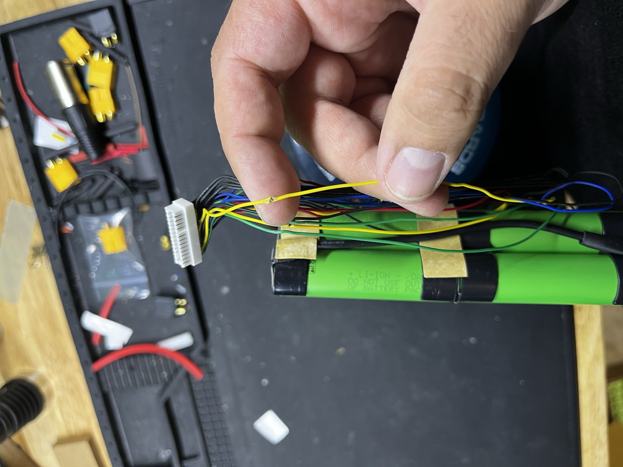


As shown in the gallery above, the heat shrink is applied to the damaged wires where needed, and then a new heat shrink piece is applied to the wire PRIOR to resoldering it to the nickel tab. Those are then heated closed. The yellow ones are the replacements, and so it can be seen that not every wire was damaged.
Once this is done, modifications to the battery enclosure should prevent further damage to the battery wires.
Testing The Battery
It a decent idea to tes the battery before it leaves the shop, so as not to send a dead or unsafe pack out of the shop. This can be done with a multimeter, of cource, however I also like to run a charge and discharge cycle as well just to make sure that the pack is at least working.
For this, I use a breakout board from Z Battery Systems, wired to an ENNOID XLITE V3 smart BMS. The main lead is wired in with an XT60 to XT30 adapter, PAYING ATTENTION TO THE POLARITY. Because, you know, Future Motion has reversed polarity in their XT60 connectors. This enables me to set the BMS to 15s, observe the cell group voltages, and run a charge and discharge cycle to make sure the groups behave normally.


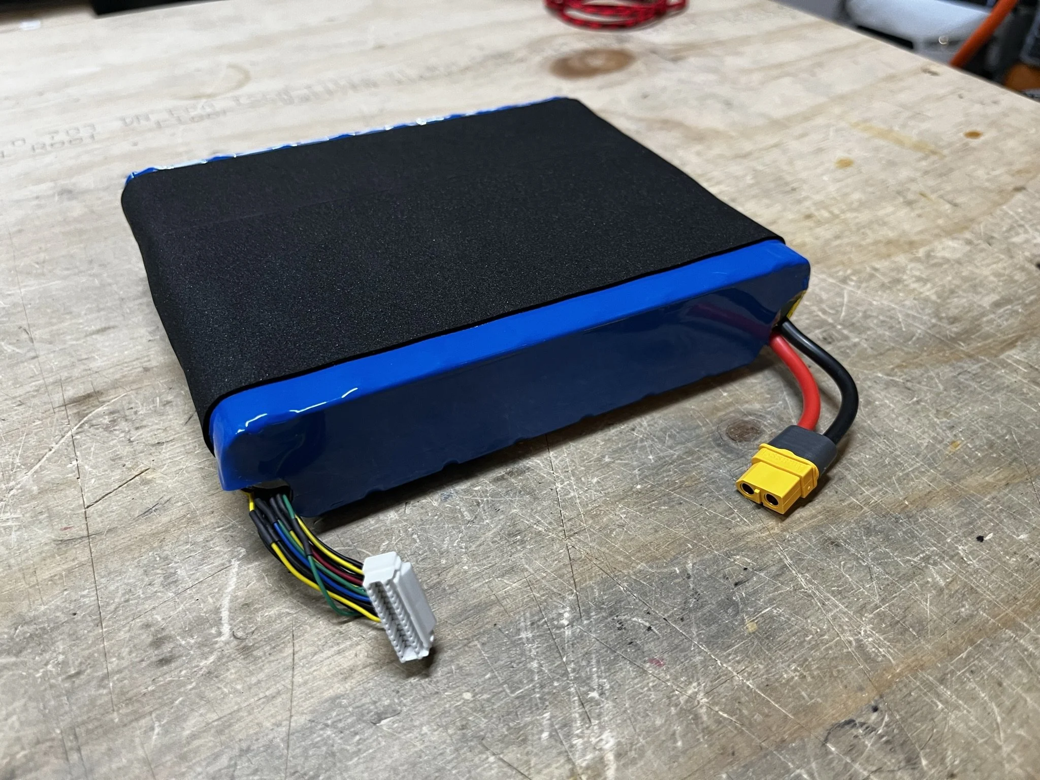
Closing Up The Battery
Closing the battery up is a matter of reversing the steps of tearing it down. The wires get secured in their original positions with Kapton (polyimide) tape, fish paper is applied to areas where the main leads with opposing voltages are touching (which will see pressure on installation), and things are fixed roughly in place before fiber strapping tape is reapplied to hold the halves and everything else together.
Heat shrink is then applied (I used 200mm flat width blue, cut to the neede size). A dense foam is then applied in the cross direction to cover the exposed tape areas.