

19s2p VESC One Wheel Battery | Build Log
This project’s content is sponsored by JLC PCB. They have been my chosen fabricator for my products before this, and so I appreciate their support.
If you choose to undertake this project, please consider using my affiliate links to support this project and future ones like it:
Discover Easy, Affordable, and Reliable PCB manufacturing with JLCPCB! Register to get $123 New customer coupons: https://jlcpcb.com/?from=TheBoardGarage
If you have CNC machining or sheet metal fabrication needs, you can also check out JLCCNC: https://jlccnc.com/?from=TheBoardGaragecnc
WARNING:
Lithium-ion batteries are inherently dangerous. They can overheat, catch fire, explode, or leak hazardous chemicals if mishandled, damaged, overcharged, short-circuited, punctured, improperly stored, or exposed to extreme temperatures.
Projects involving lithium-ion batteries are dangerous by nature. Working with these cells carries risks of thermal runaway, burns, toxic fumes, fire spread, and property damage. Only qualified individuals should assemble, modify, or repair battery packs. Use proper protective equipment, properly specified chargers, battery management systems (BMS), fuses or protection circuits, appropriate insulation measures, and safe charging/discharging practices. Always follow applicable safety standards, and local regulations. If you are not experienced or trained, do not attempt battery pack assembly.
Part 1 - Design Thoughts, Desired Outcomes, Rationale
Why 19s2p? To explain that, I’ll give some context. This covers a bit of history, and a battery failure I experienced 2 years ago.
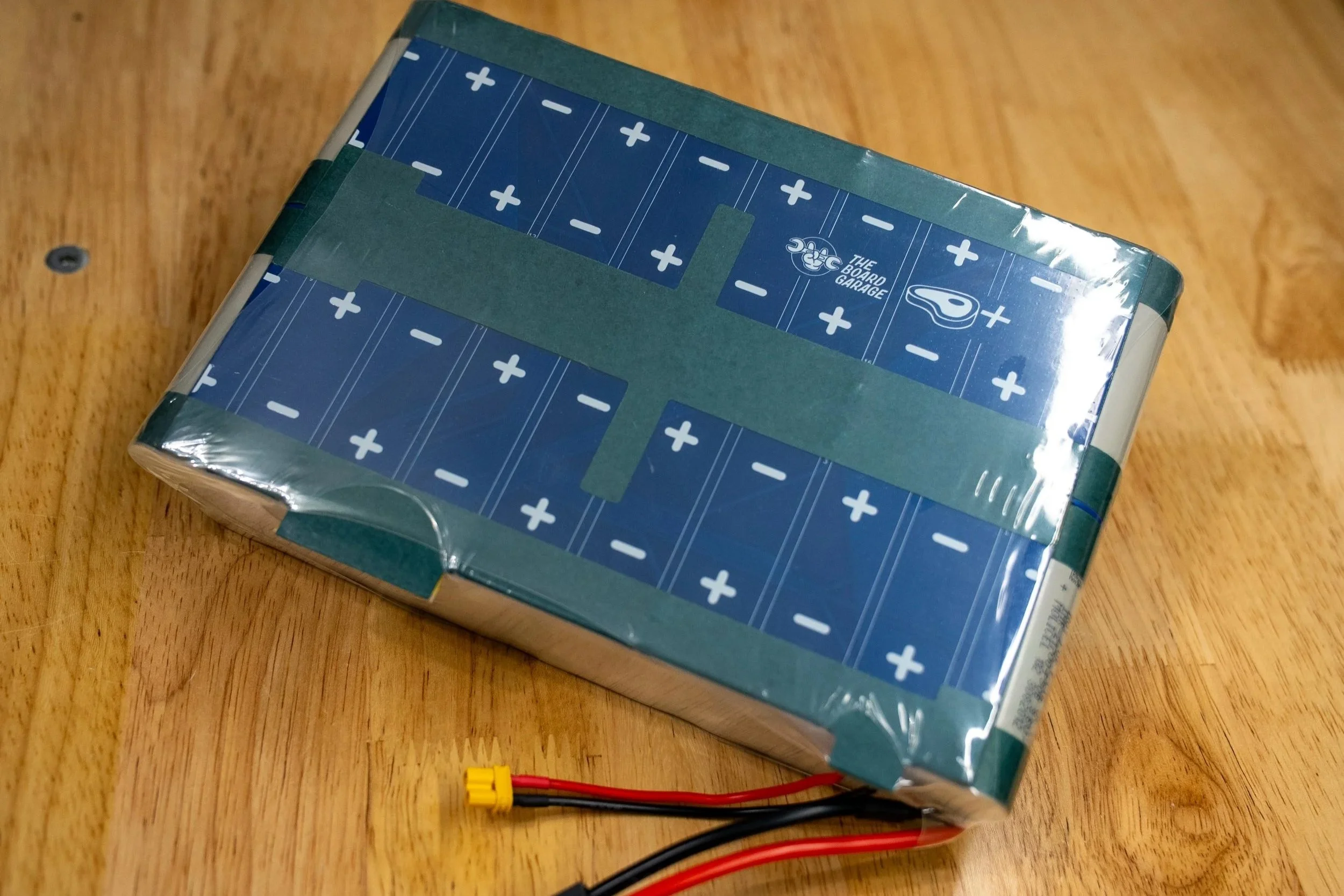
Back a few years, the original TORque Box from The Float Life and my accompanying 18s2p battery configuration were just about the best all around power option for a self-built, DIY style one wheeled board. Most people at this point call it a VESC one wheel, since it’s a one wheeled balance board that uses VESC based motor control. Since there is a good amount of information on that topic itself already out on YouTube and the social media groups for Onewheels, I’ll skip the lore of “VESC Onewheel” here. I bring this topic up here, because that old style 18s2p battery configuration was the most robust, reliable, and easy to install battery setup for these kinds of projects, and I’m proud of the “ME4T/MEAT Pack” and its history. There are many of them still running in boards, and they remain as having the lowest failure rate of all the third party battery options for VESC based one wheel builds.
The original MEAT Pack, now retired. Surrounded by the bones of its successor.
As time goes on though, things change, and so do expectations. In line with that, I wanted a little bit MORE. A bit more range, a bit more power, a bit more battery.
At first, my impulse was to take the existing 18s2p configuration and add more cells to the front enclosure of the board. Since Fungineers was working on new box designs at the time (this coincided with the Thor Box release, and Mo at Fungineers spoke with me about cell fitment in the front box), I was leaning in that direction. However, after having my own split pack installation in testing for months, I came across a critical issue. The long and short of it is, that installing a split battery pack (a modular one, since the front cells are a module on their own) with a non-modular BMS poses a dangerous risk of the ground location shifting when the series connection within the battery is broken. This is what happens when the front and rear modules of the pack are unplugged. The load (the VESC) remains connected, and so the ground location of the system changes, and the BMS sees voltages and polarities that it was not designed for.
What this results in, is BMS failure. Specifically, BMS failure that can lead to uncontrolled heating inside a sealed battery enclosure.
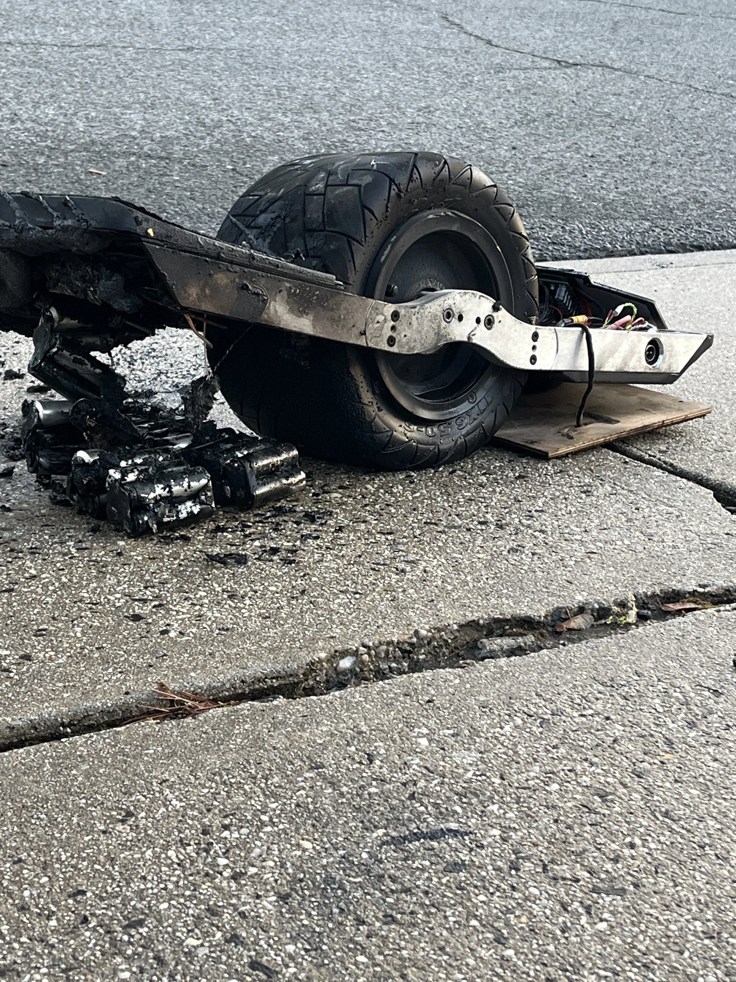
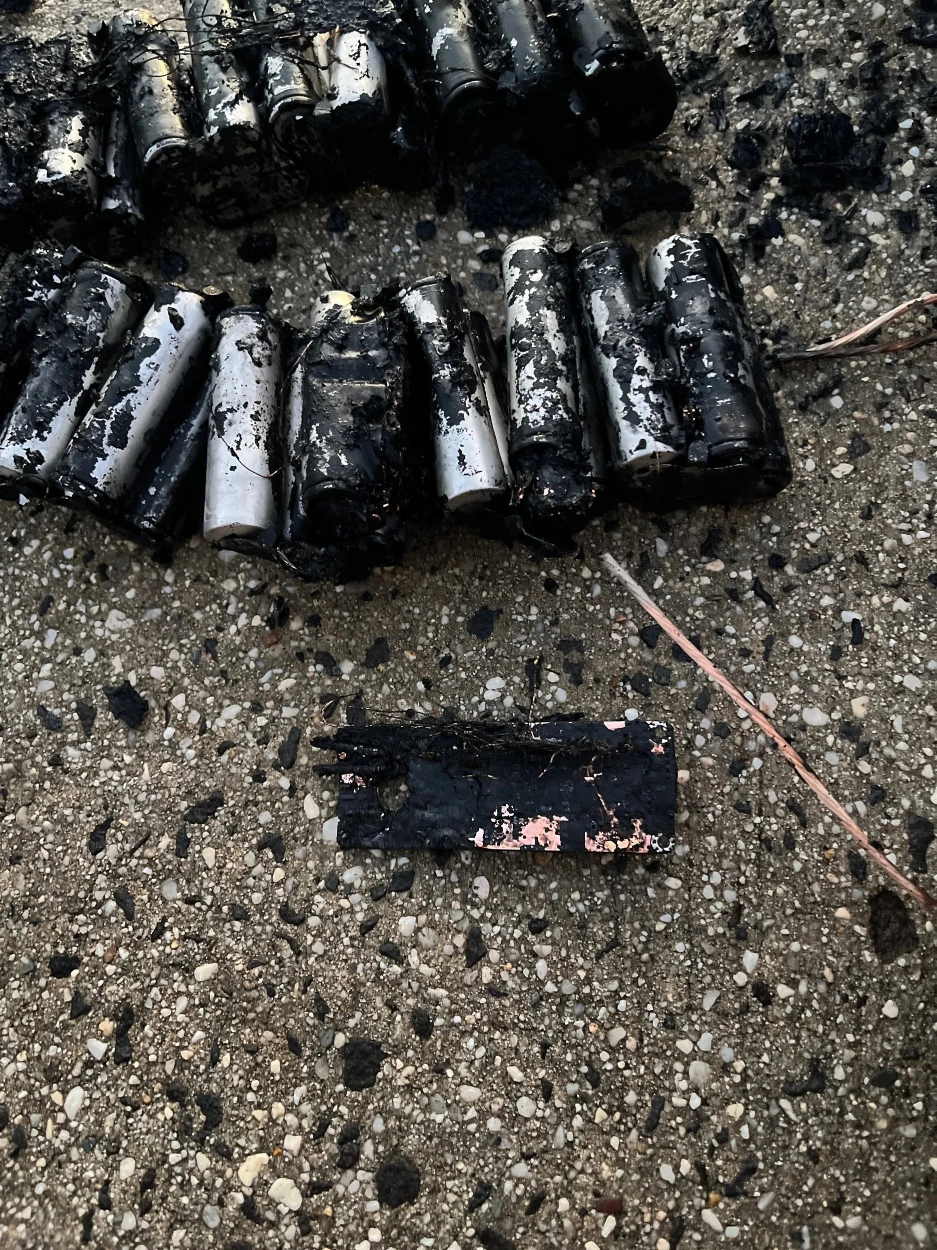
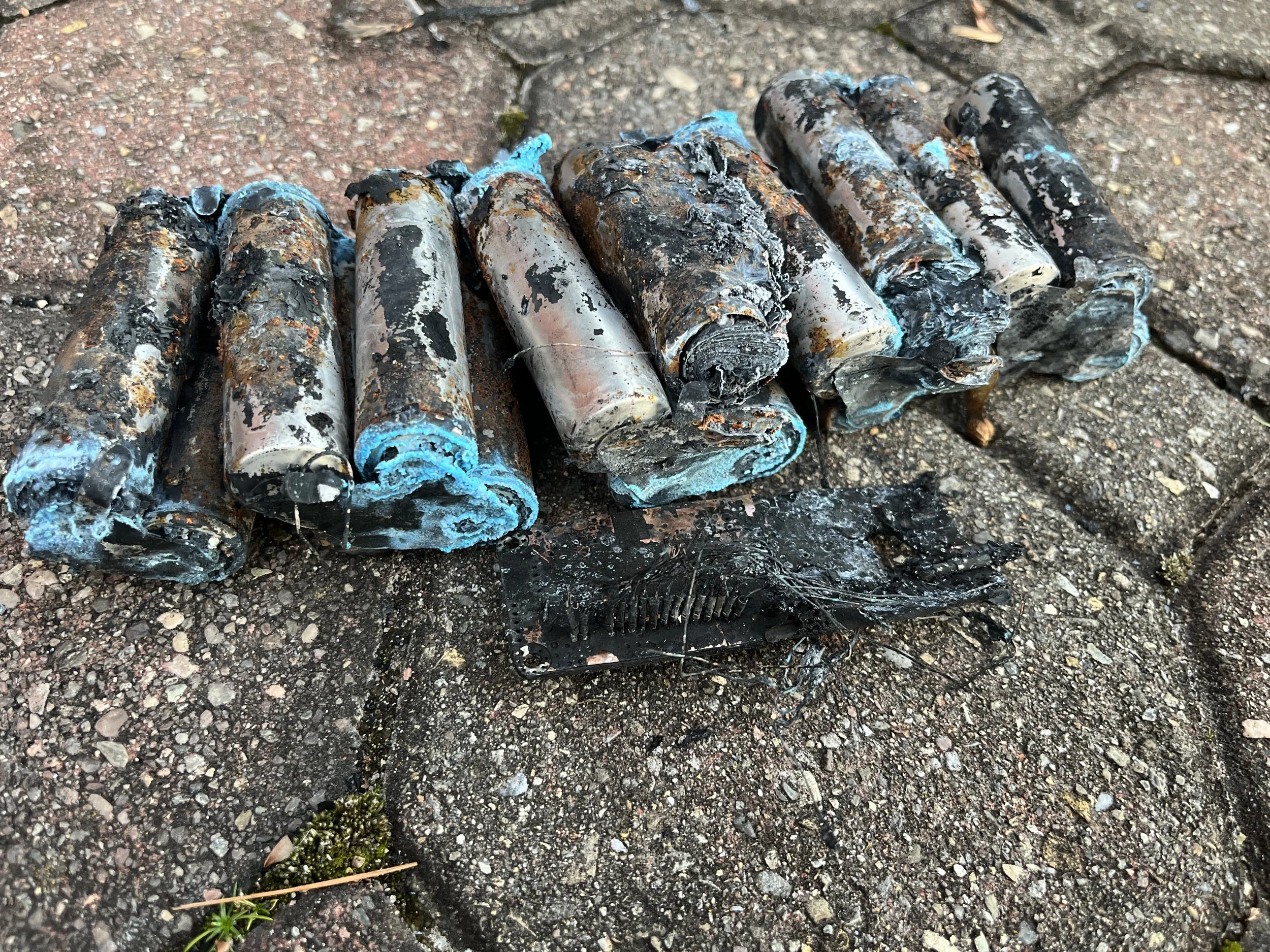
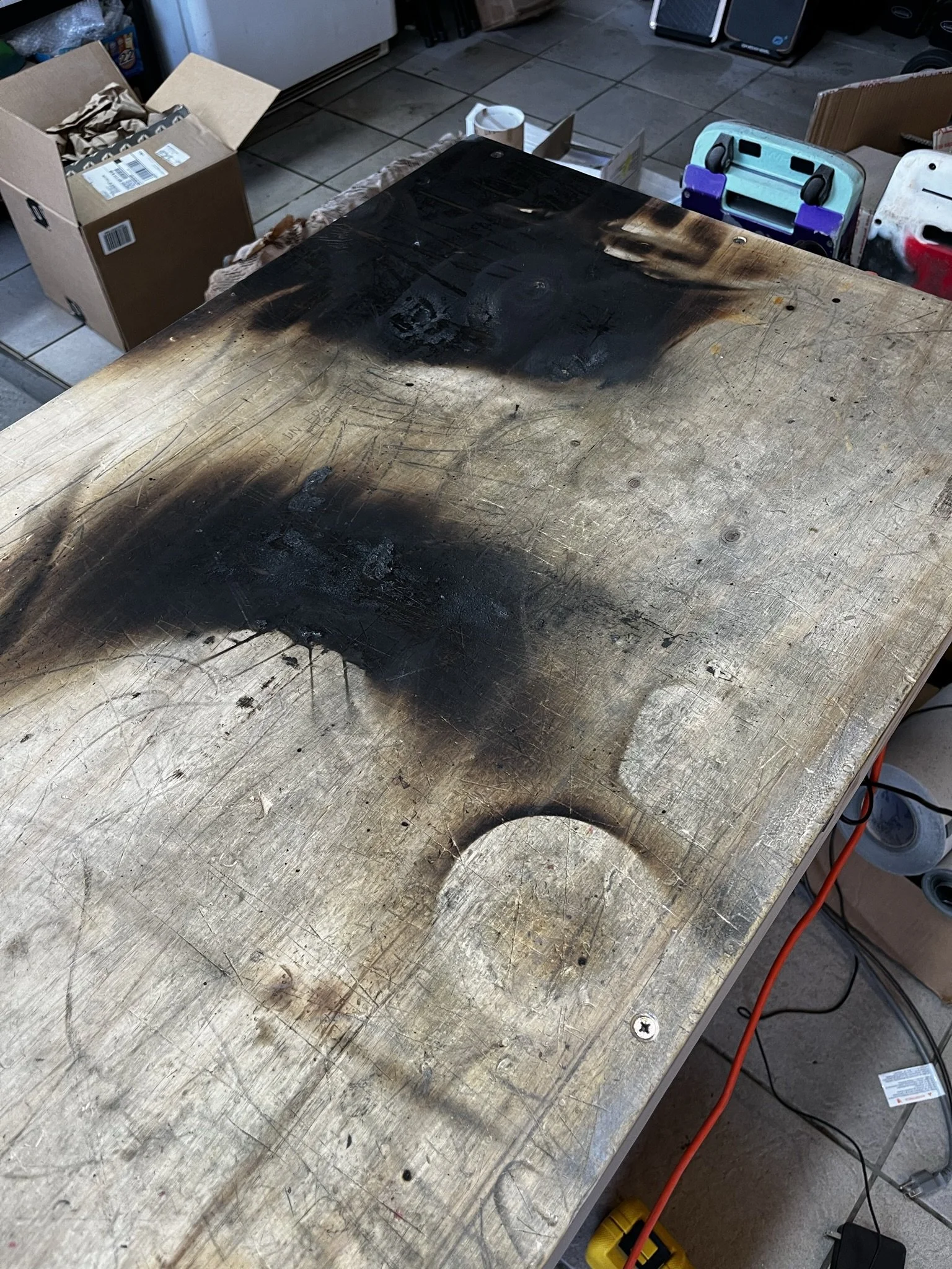
In my testing, this led to a fire. Not just a fire, though. A fire that consumed the board, burned my bench, and started while the board was OFF and UNPLUGGED. Which is the worst condition of a battery fire possible, since there was no outward cue of a failure, and I was not present. I returned to the garage at the moment that the board began erupting smoke and fire.
Here is what remained of my split pack:
Fast forward to 2025, and I was looking for options for a new battery design for my projects. While other battery builders were seemingly glad to lean into the 18s2p/2s2p split pack, I wanted nothing to do with it. Oddly enough, there were and still are builders who insist that split pack layout is fine, citing their own specific examples of “2000 miles with no issues”, even with monolithic (non-modular) BMS units. Despite my attempts to explain how risk of system failures work, it’s not my problem to solve and naturally, any project success is a good thing. No one wants anything to fail. And I would not wish my experience on anyone.
Either way, a different approach felt more prudent and so I reached out to an old friend and colleague of mine who had extensive experience with PEV battery design in general, and more specifically, PCB based battery packs. He and I have long shared outlooks on battery assembly, and also share a similar experience-based fear of lithium ion batteries. And because of that, I believe we have a more grounded and realistic respect for the technology.
Over the span of a few months, he and I arrived at the new pack shape. It takes the old 18s2p idea, shifts the layout, and adds one more group of cells to the empty “shoulder” in order to arrive at a similar pack design, but with just 2 more cells. Electrically speaking, it is literally the middle ground between the old 18s2p brick, and the larger 20s2p arrangements.
A perfect medium.
Part 2 - Parts & Manufacturing
This battery design has a few parts to it, and each part is made up of different parts. Parts on parts. I will do my best to lay out each part and its constituent parts. #parts
Specialty Tools
These are some of the more targeted tools that I use generally for building battery packs and working on board projects.
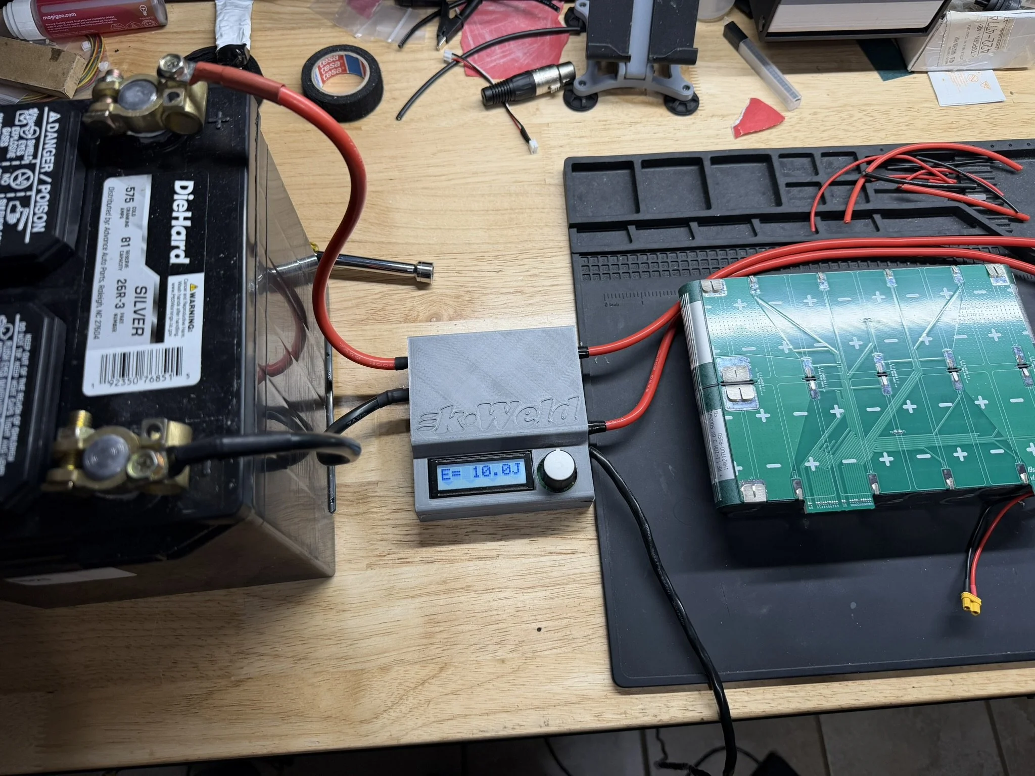
KWeld Spot Welder
^This is the welder I use. Others have had good luck with other models. Please ask in the “Vesc Onewheel Builders” Facebook group and the Vescify Discord server for suggestions on welders if you’re looking to get into these kinds of projects.
Incidental Parts
While much of this design uses custom or specialty parts that need to be ordered from manufacturers, there are some parts that are more generalized for this kind of project. I will link them below:
21700 Insulator Rings (necessary)
12AWG Silicone Wire (for discharge circuit)
18AWG Silicone Wire (for charge circuit)
*Select heat shrink sizes are needed for the above wires, ideally in red and black to suit.
PLA Filament (for assembly/alignment jigs)
PCTG Filament (for insulators/dividers/caps)
Double Sided Adhesive Tape (for mounting the PCB to the battery pack)
Molex PicoBlade 10-pin Harness (for making BMS adapter harnesses)
Molex PicoBlade 2-pin Harness (for making BMS adapter harnesses)
100K Thermistor (temperature sensors)
0.5mm ID Silicone Tubing (temperature sensor insulator)
10mm Neodymium Magnets (for welding jigs)
200mm Flat Width PVC Heat Shrink
250mm Flat Width PVC Heat Shrink
Fabrication Files
This ZIP archive contains the digital files used for making this battery pack. The files are separated into their respective folders are they apply to the assembly process.
3D Prints
This folder contains BOTH the files for the pack insulators and the assembly jigs. There are some important things to note about these models.
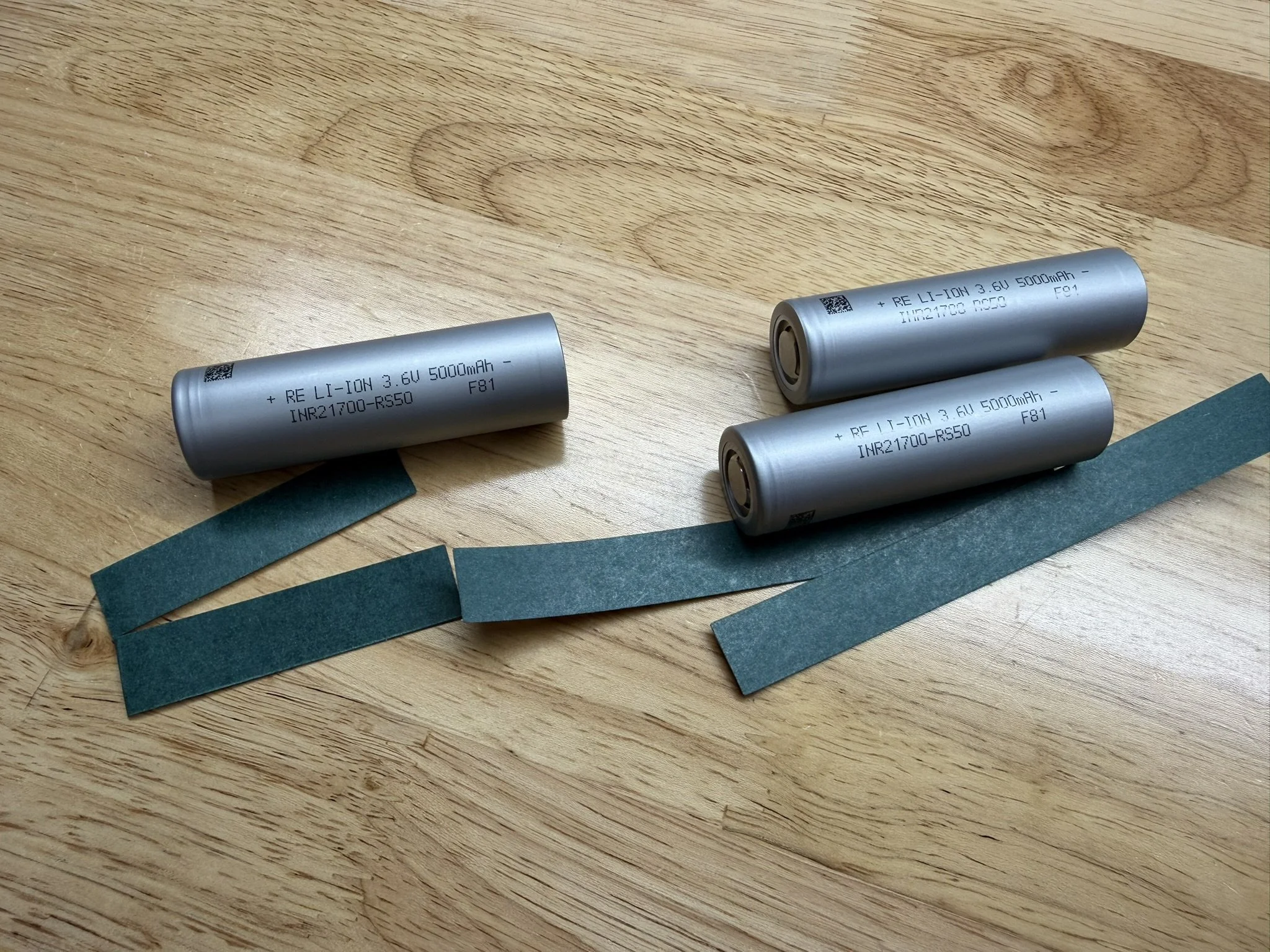
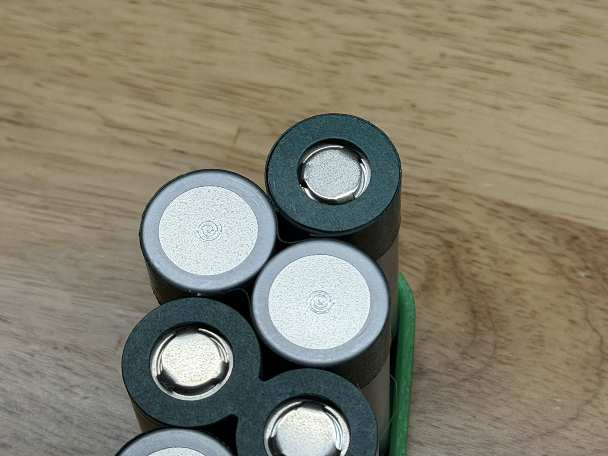
Regarding the insulator prints. These are to separate the pack halves from each other as well as cover over the ends. Note that the center insulator has key shapes in it, and these key into the PCB. More will be shown later during the assembly. These models are sized for Molicel cell cans. The P45B, the P50B, P42A, cells like those. Cells like the Reliance RS50 are slightly smaller. DO NOT RESIZE THE CENTER INSULATOR. It will misalign the PCB keying pattern.
What I did for the RS50 cell pack, is simply trim the end caps with some scissors to slightly fit better, and give some more clearance to the wiring harness when installing it into the box. After that, I resized the end caps a bit to suit the narrower pack due to the smaller cell size. All I did was reduce the object in the slicer, the X axis to 99%, and left the other axes the same.
Regarding the assembly jigs, the above cell size information is applicable. These jigs were printed on a Bambu X1 Carbon in Polymaker Polylite PLA. Your printer and filament may vary in how the resulting jigs fit, and so it is advisable to check them. I made some adjustments to my prints in some cases, and used a variant for other cases. I will include some extra files with different clearances, in the even that the included files don’t fit as needed.
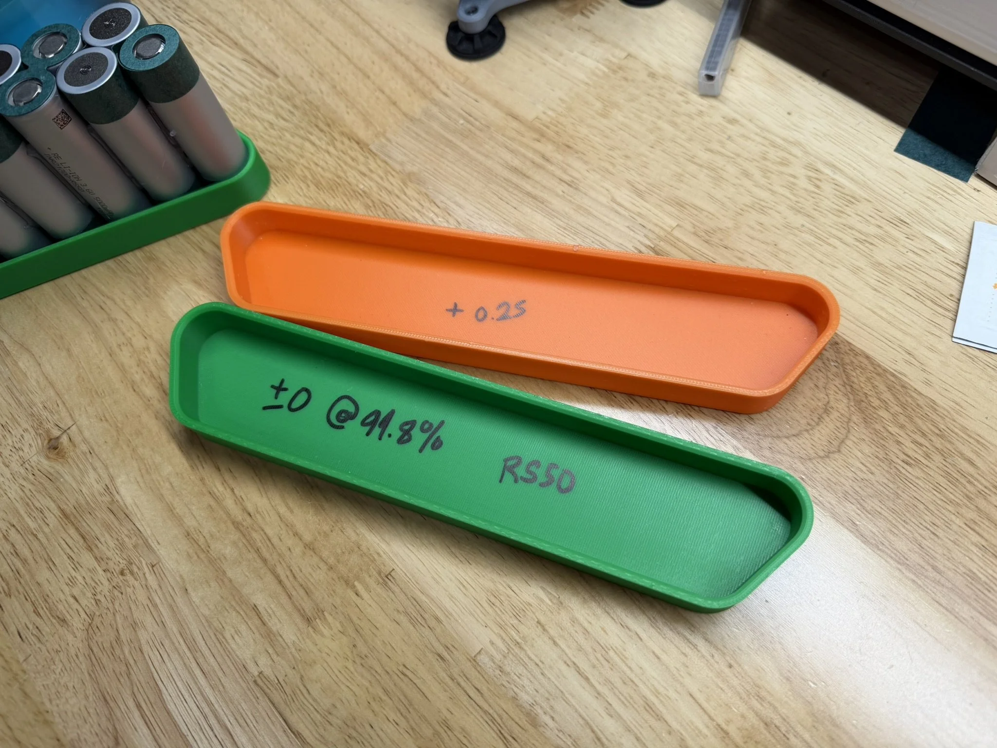
In addition to the included print files, I’ll link the print plates and alternate versions of what I’ve printed. Note that there are variants with different tolerances in both positive and negative directions. See below photos of the ones I used myself.
3MF of Tire Side End Cap - RS50 Sized
3MF of Tire Side End Cap - Molicel Sized
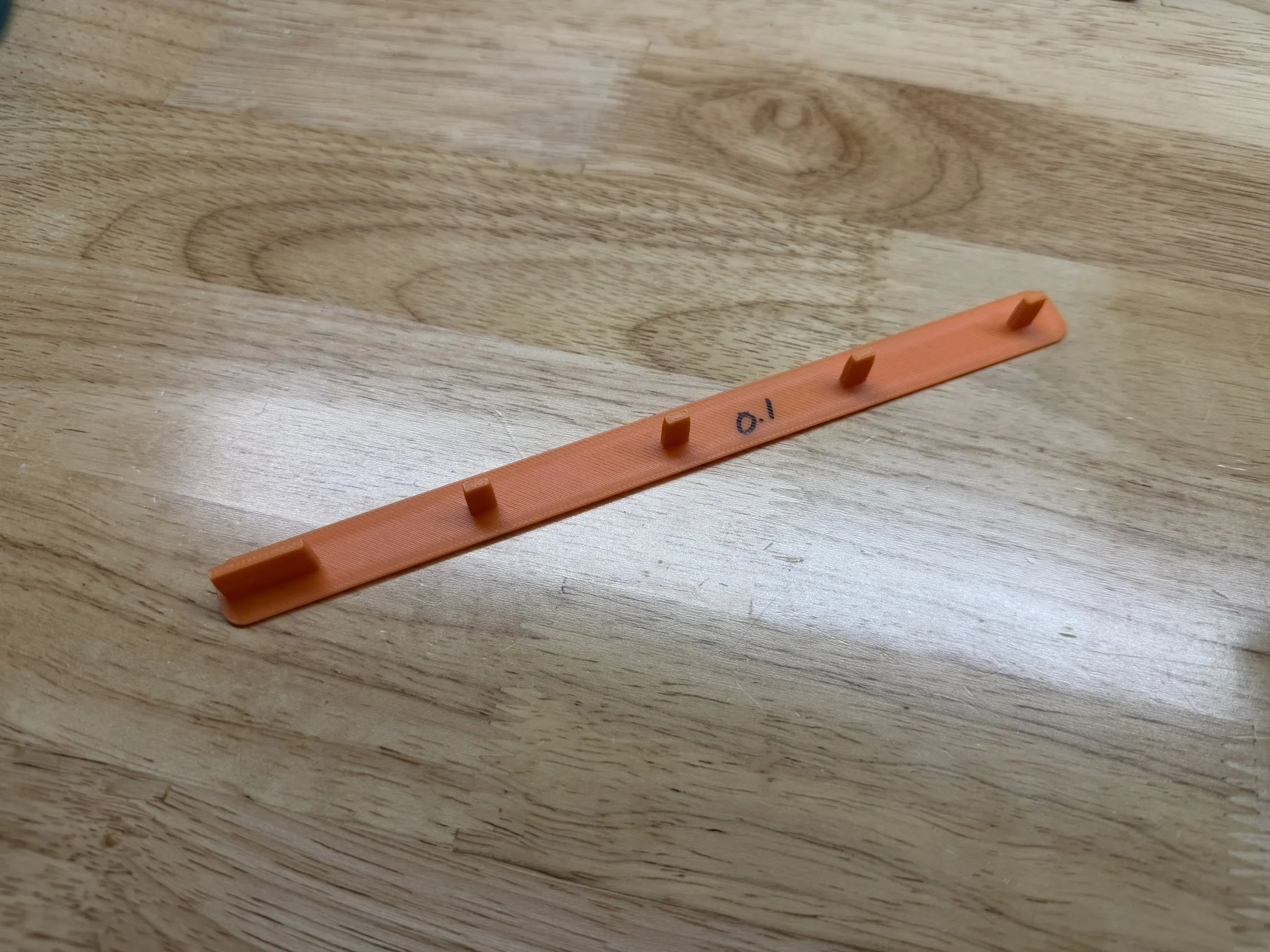
Fish Paper Install Jig - No Clearance
Fish Paper Install Jig - 0.1mm Clearance
Fish Paper Install Jig - 0.2mm Clearance
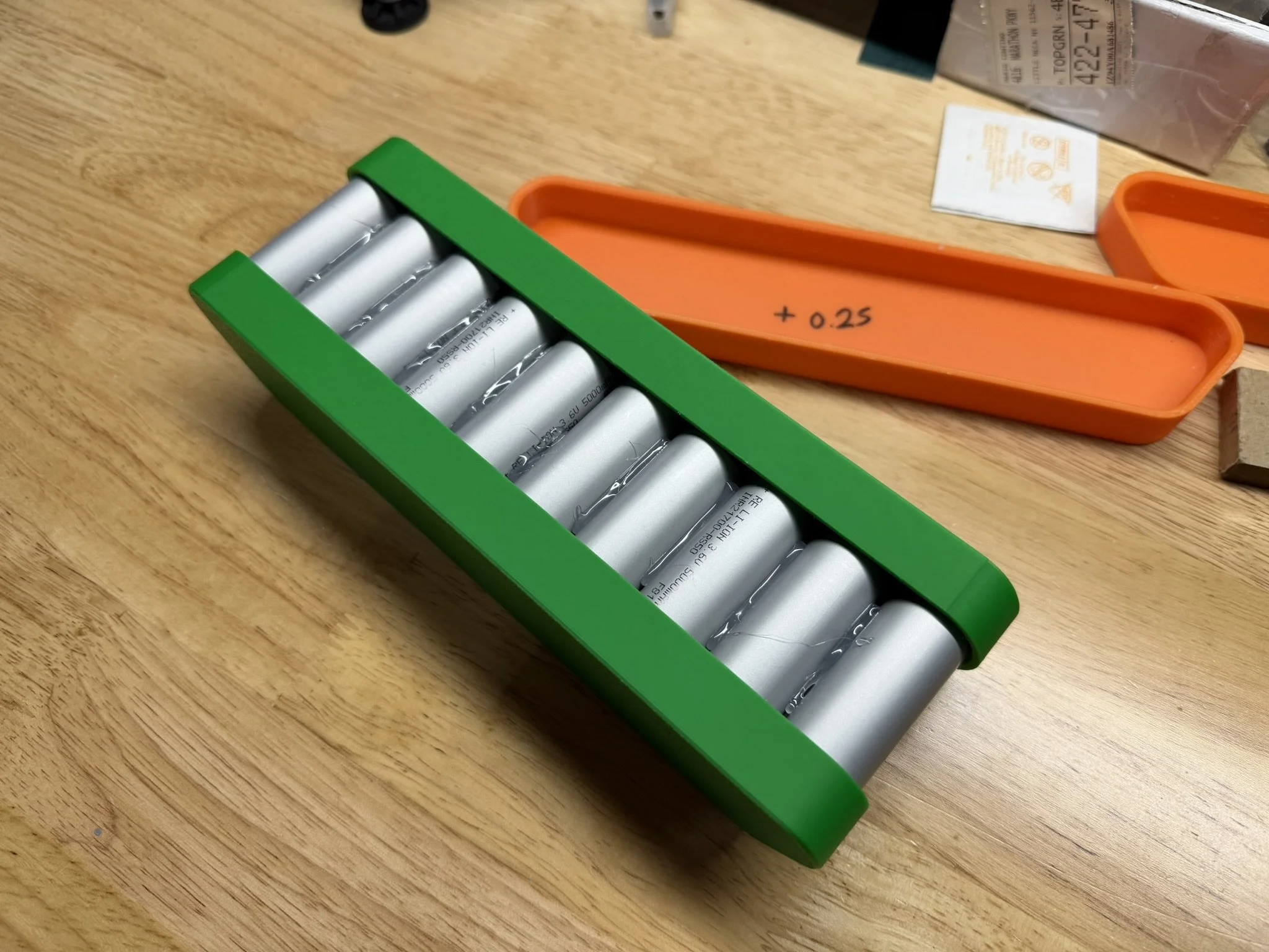
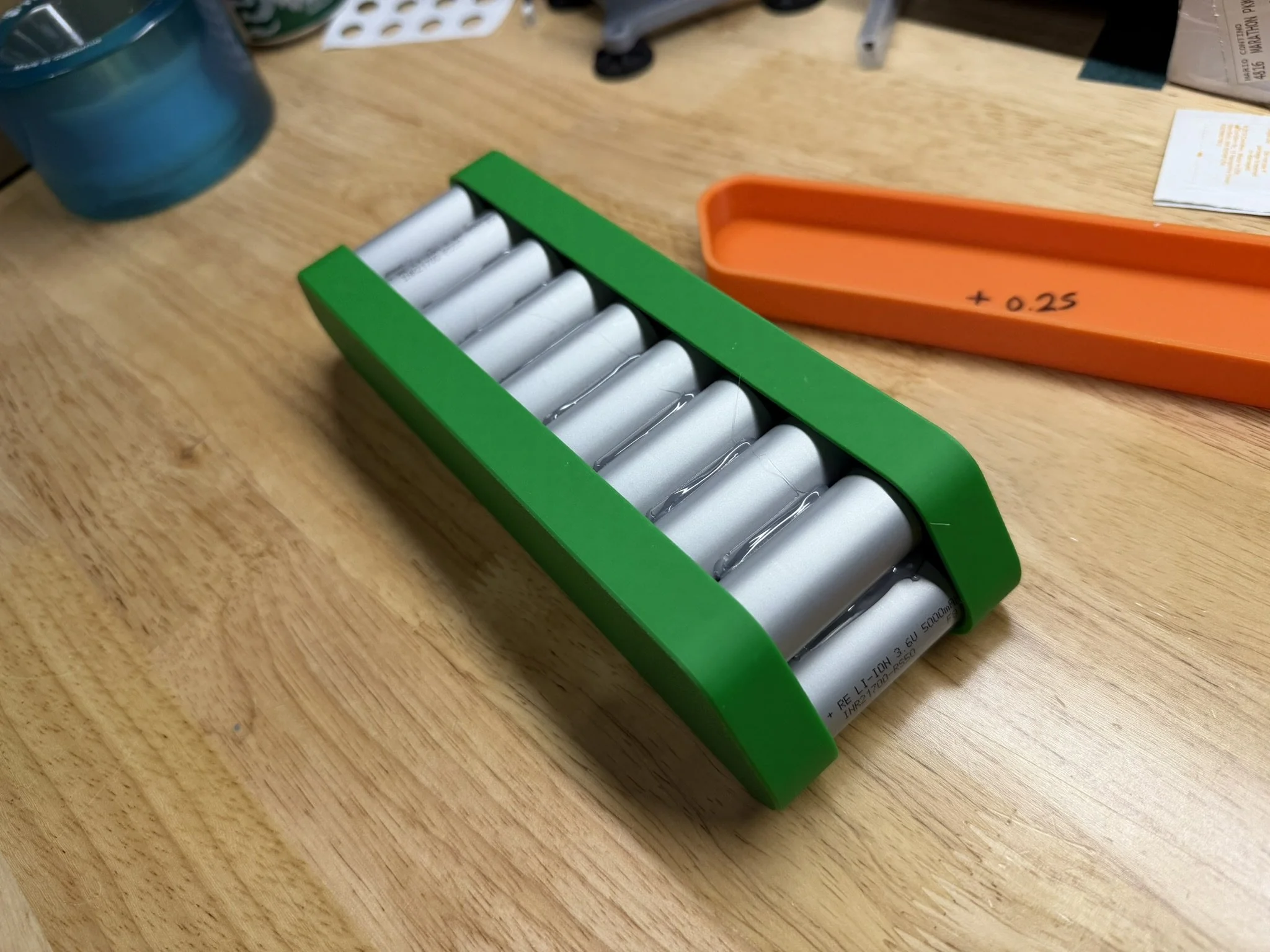
Cell Glue Jig - 0.25mm Interference


Fish Paper Shapes / Insulators
There are a number of fish paper shapes that are used in this design. Fish/barley paper is a common, age old insulation material used in battery packs. The included files for this project include 4 custom shapes that need to be cut on a 2D plotter of some kind, as they are shaped to the PCB itself. In addition to that, the battery pack cell brick itself requires a basic rectangular shape to be cut. I’ll explain each type of cut below.
Custom Fish Paper Cuts
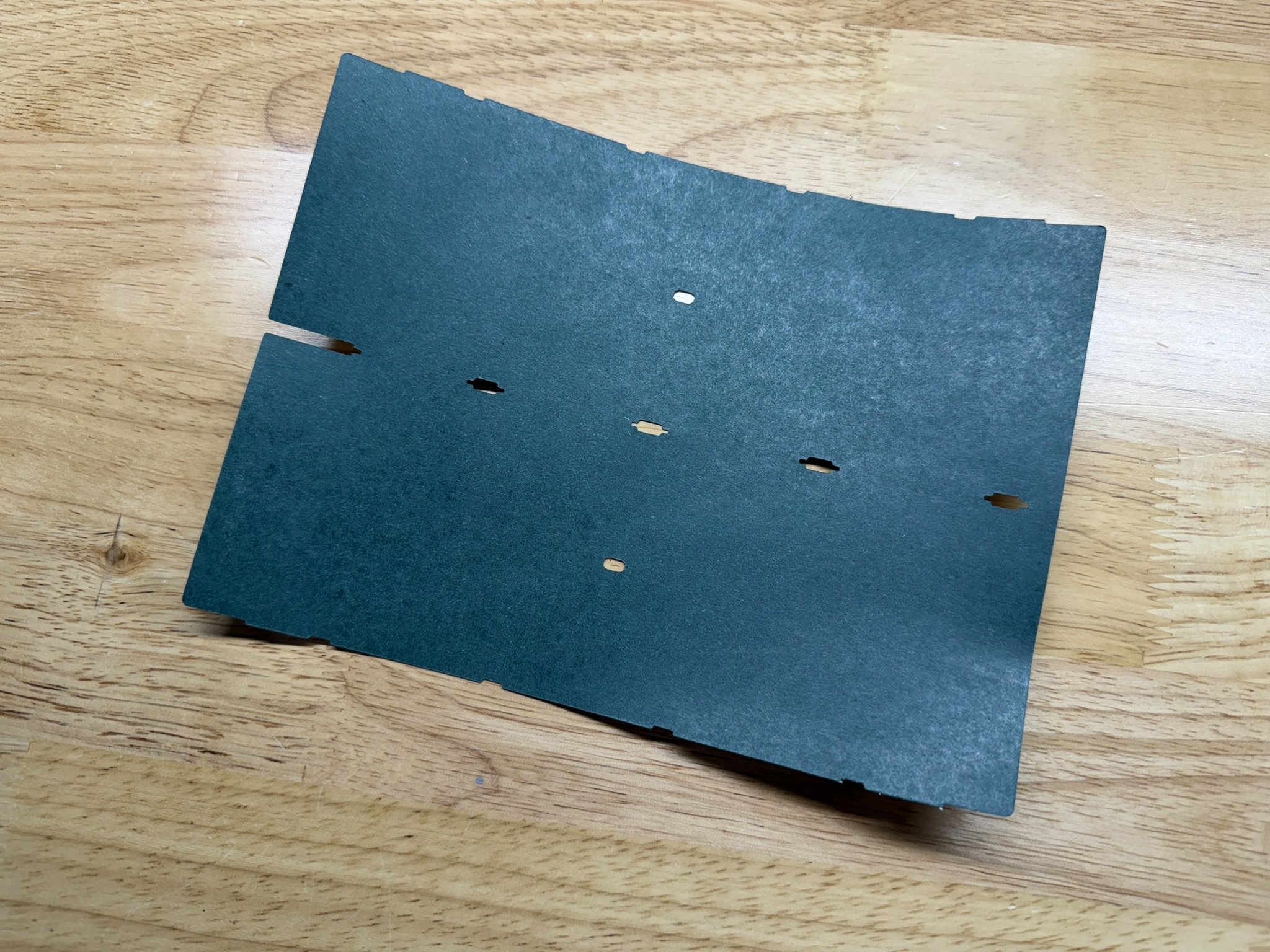
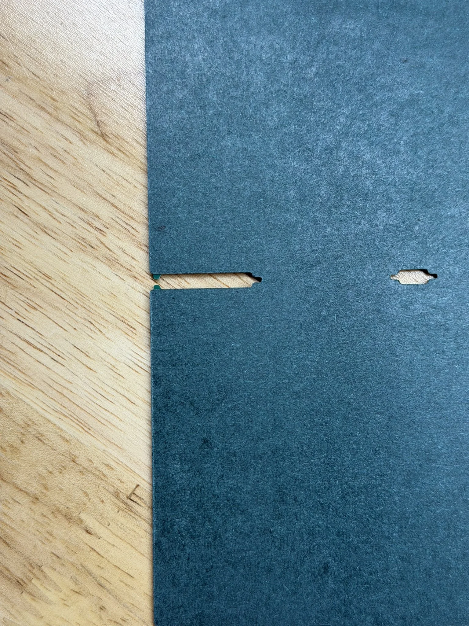
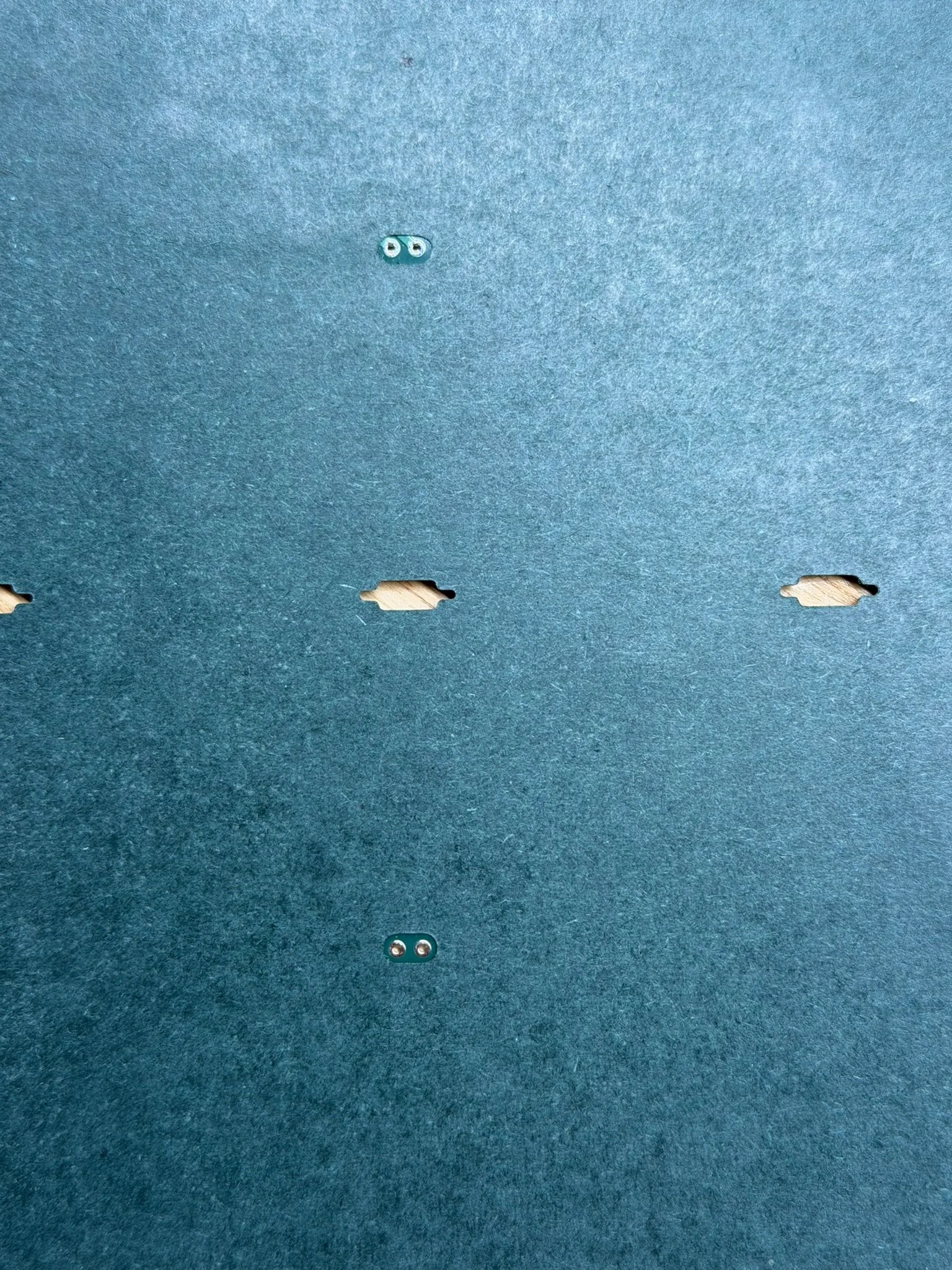
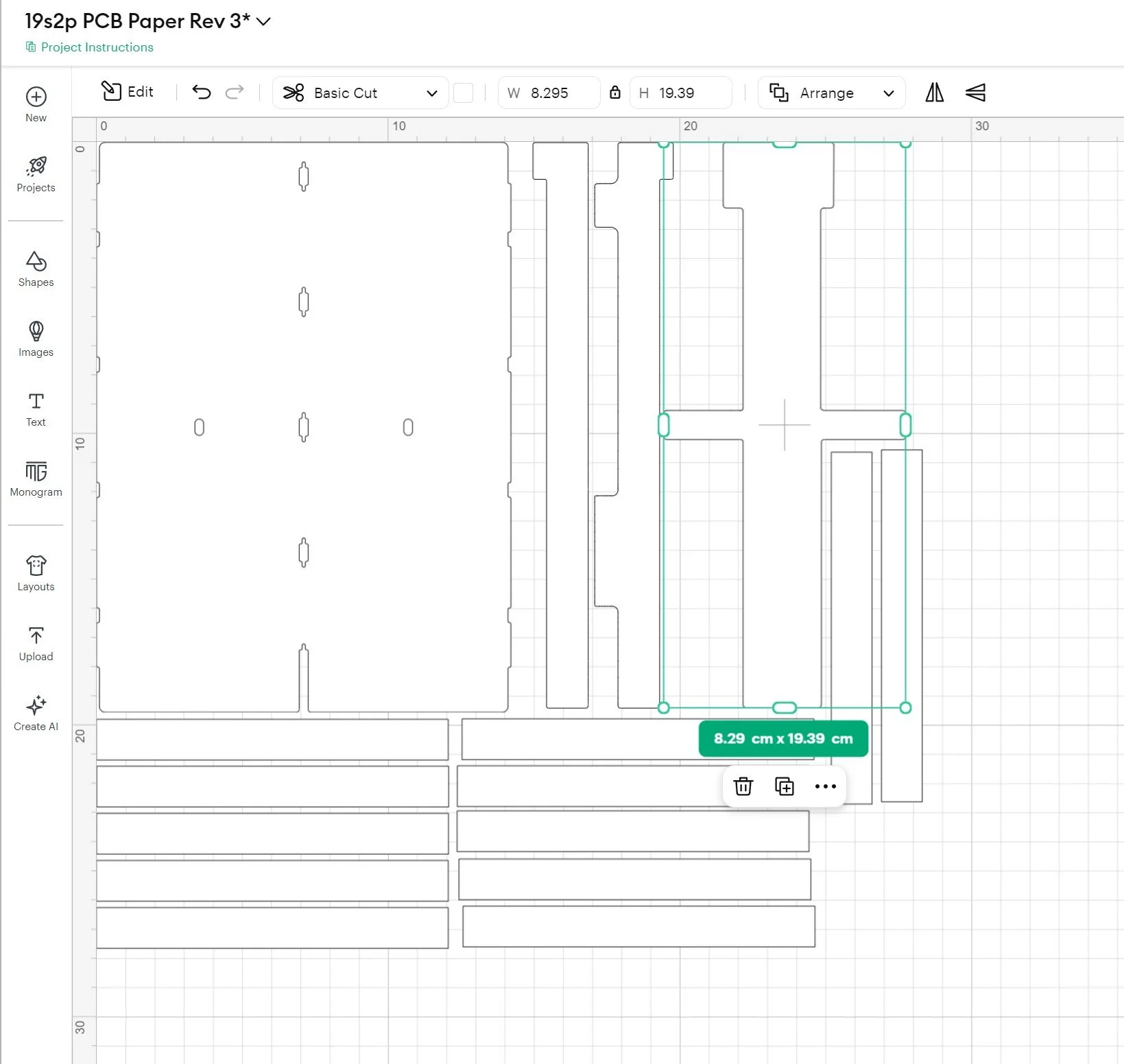
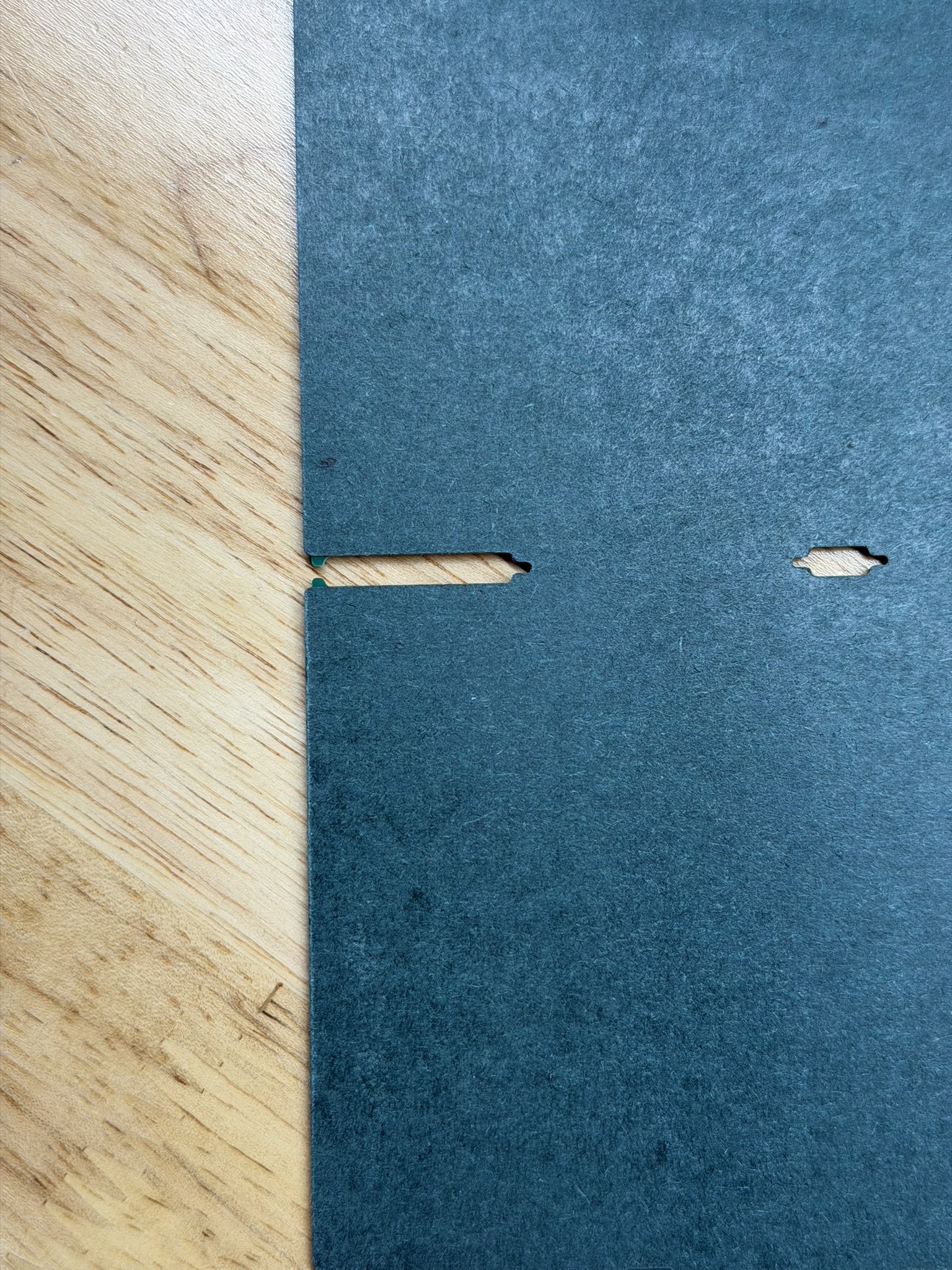
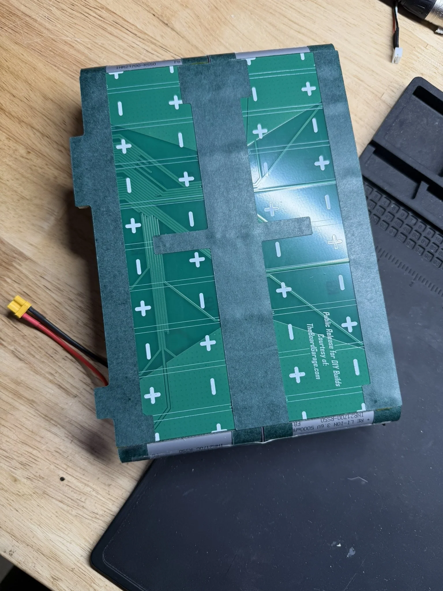
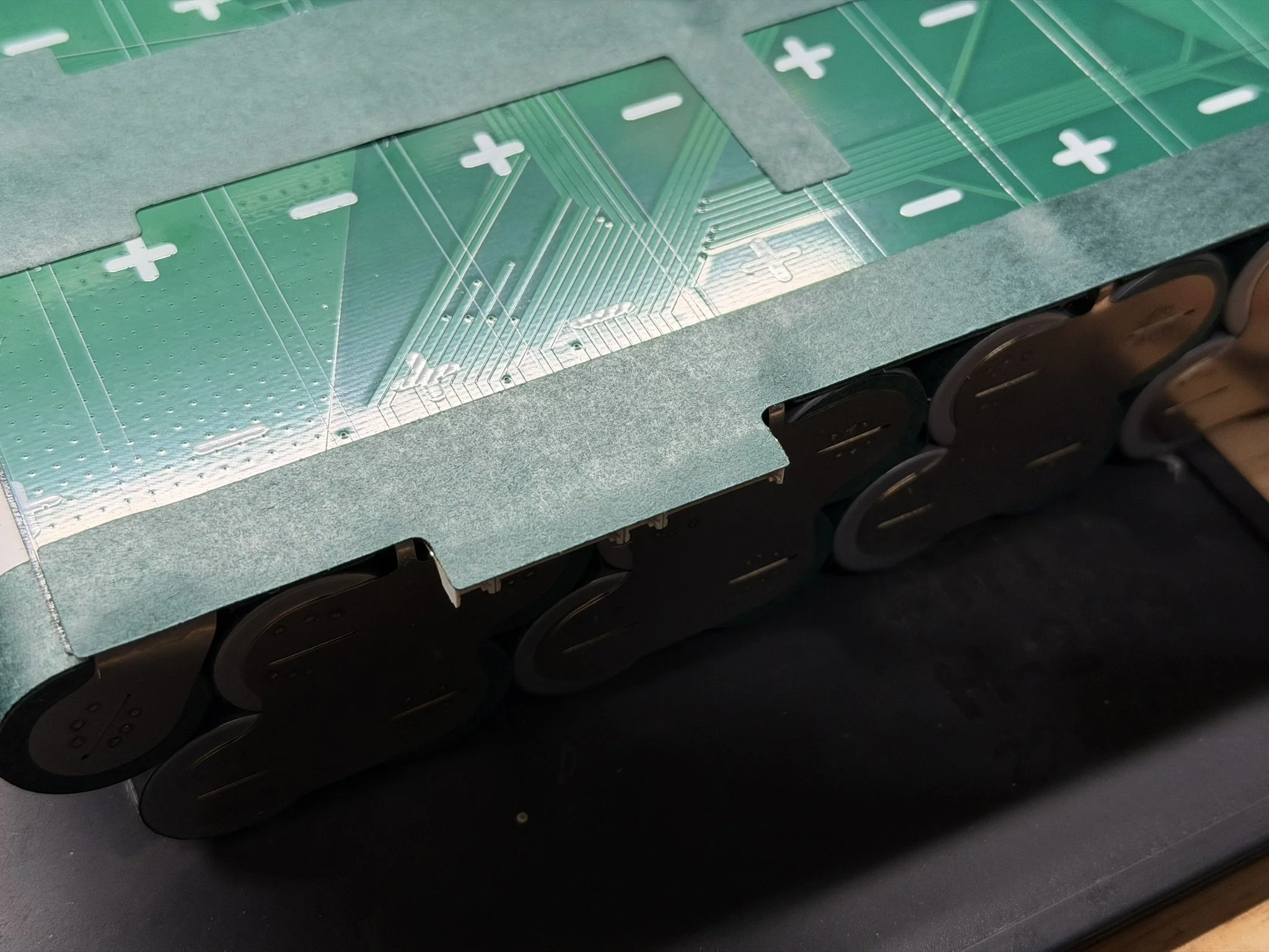
The most critical and important shape to cut is the insulator for the underside of the PCB. The fish paper shape contours to the underside of the PCB, extends beyond the edge of the PCB, and contains cutouts to receive the nickel shapes as they fold over and engage with the PCB. Note the reference images below. This gets installed with the 3D printed installation jig. That jig file is included in the files package, and fitment variants are also linked above. Make sure that your printed jig fits properly in the PCB without any play or wiggle.
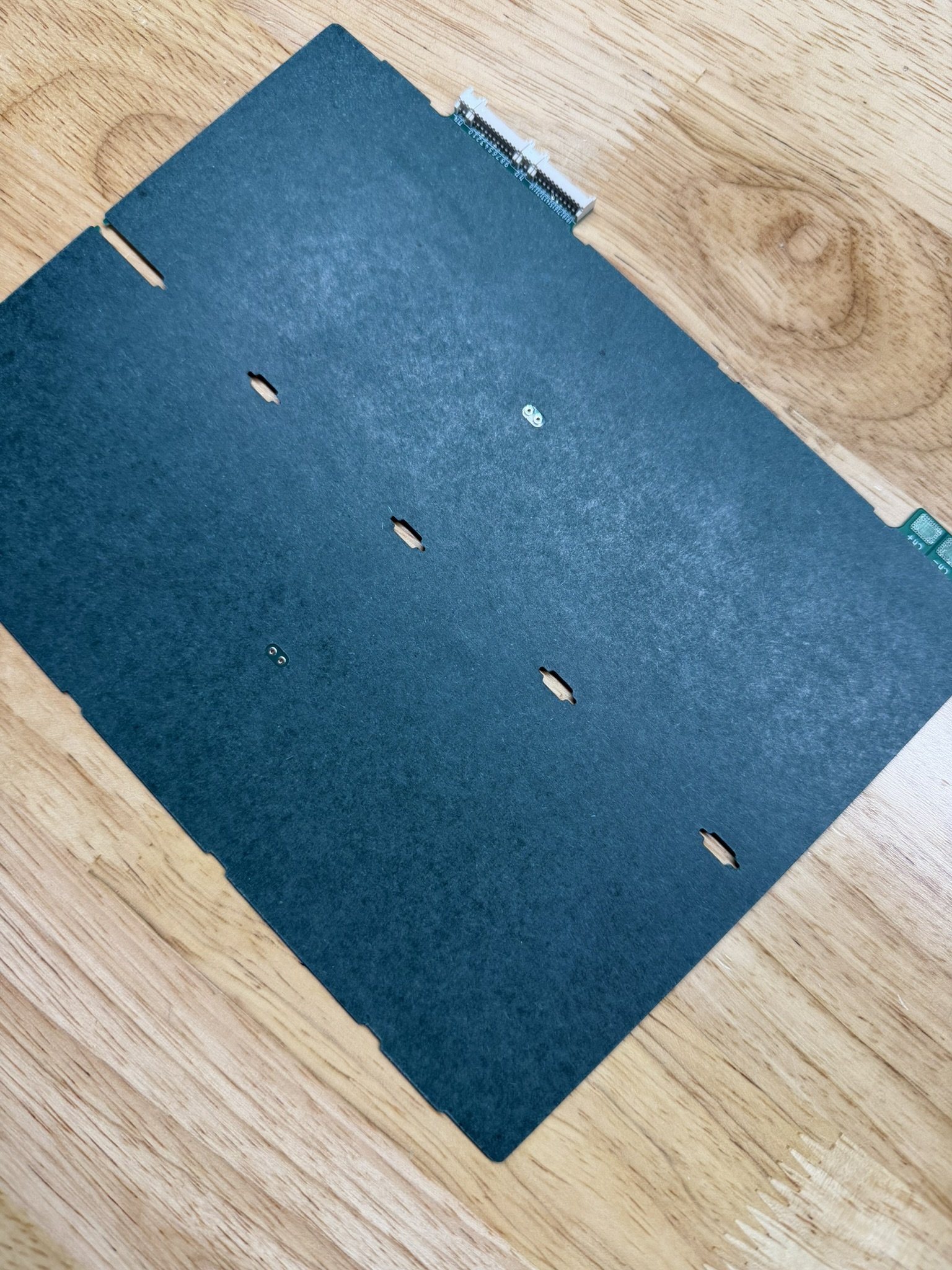


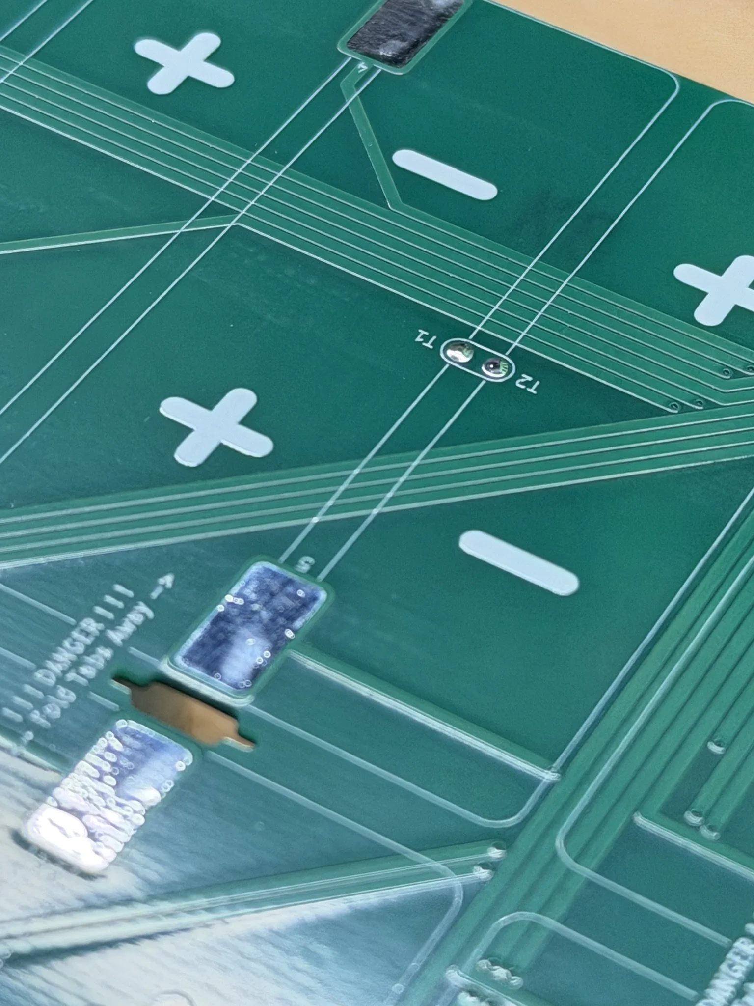
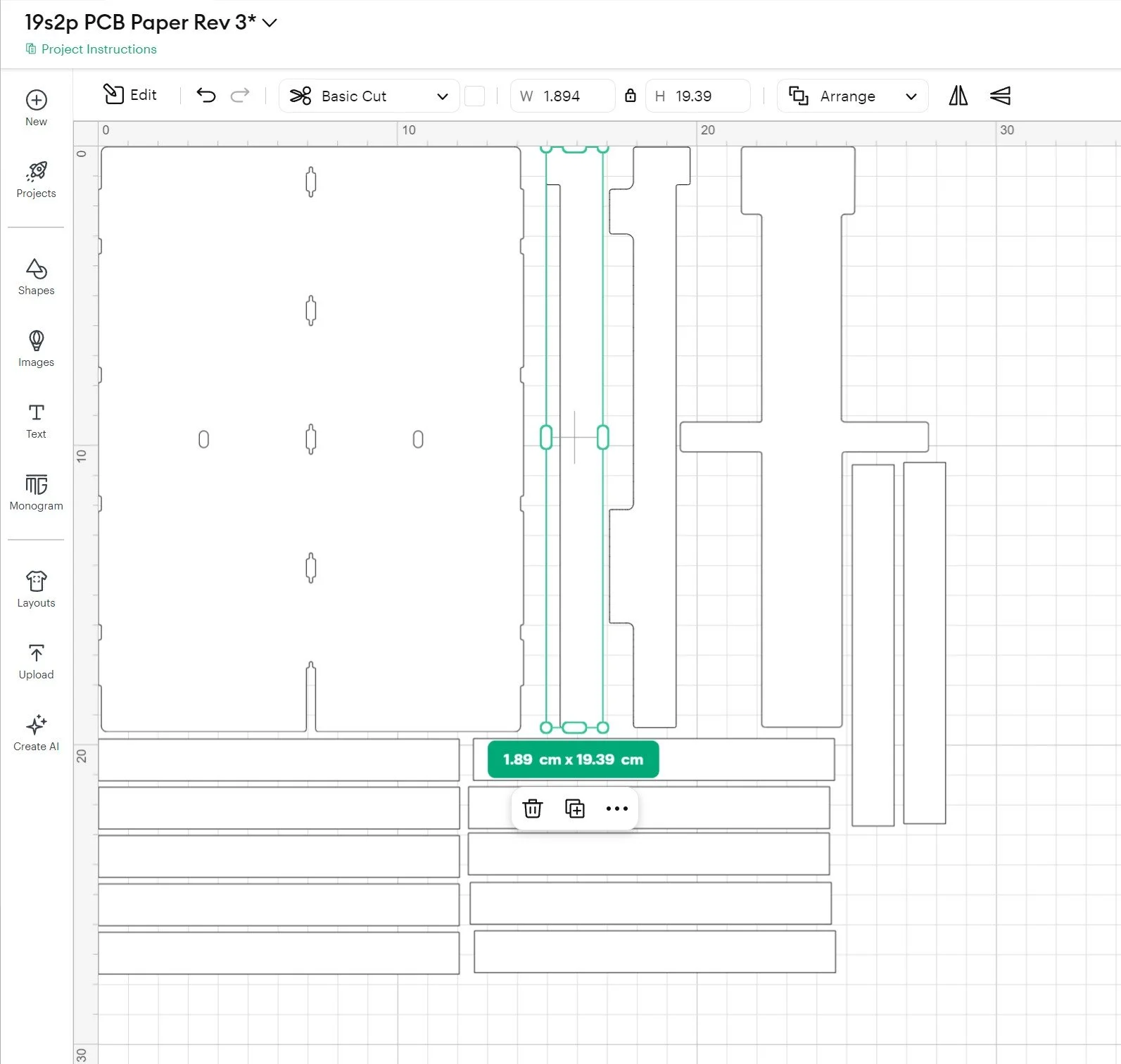
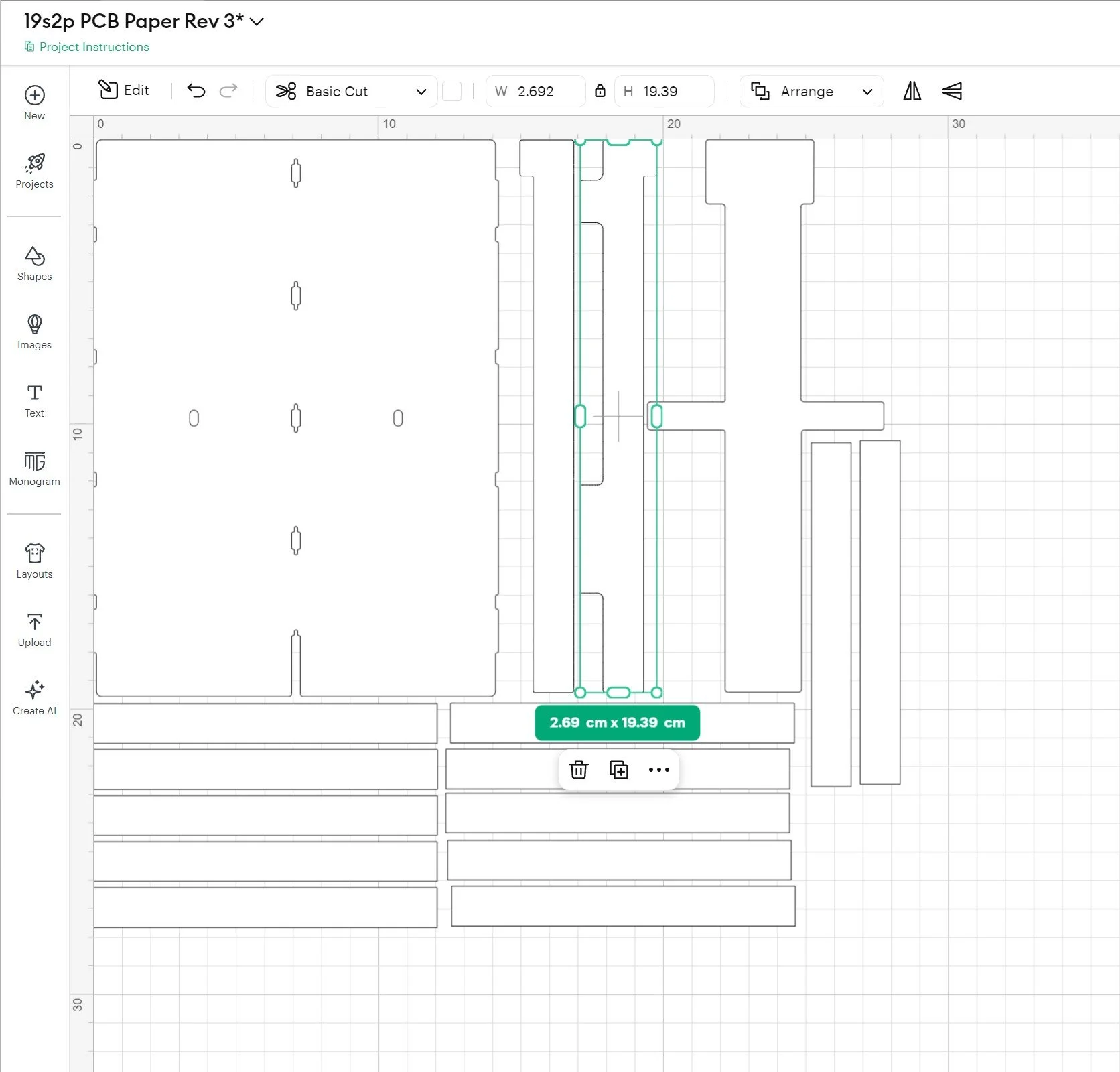
These kinds of shapes were cut on a Cricut Maker 3, and so I can only offer guidance on how I set the sizing and fitment of this shape. It’s important to have the nickel tab holes line up properly between the PCB and the fish paper cut. If it’s misaligned, there will be obvious insulation gaps, which would be dangerous. I took the measurements of the PCB itself, and used that to true up the fish paper cut within Cricut Design Space. It took about 3-4 tries to get the paper to completely line up with the PCB and the install jig, and once that was done, I saved it in the software. Unfortunately, I can’t share a Design Space file, but I will include an image of the final measurement in the software.
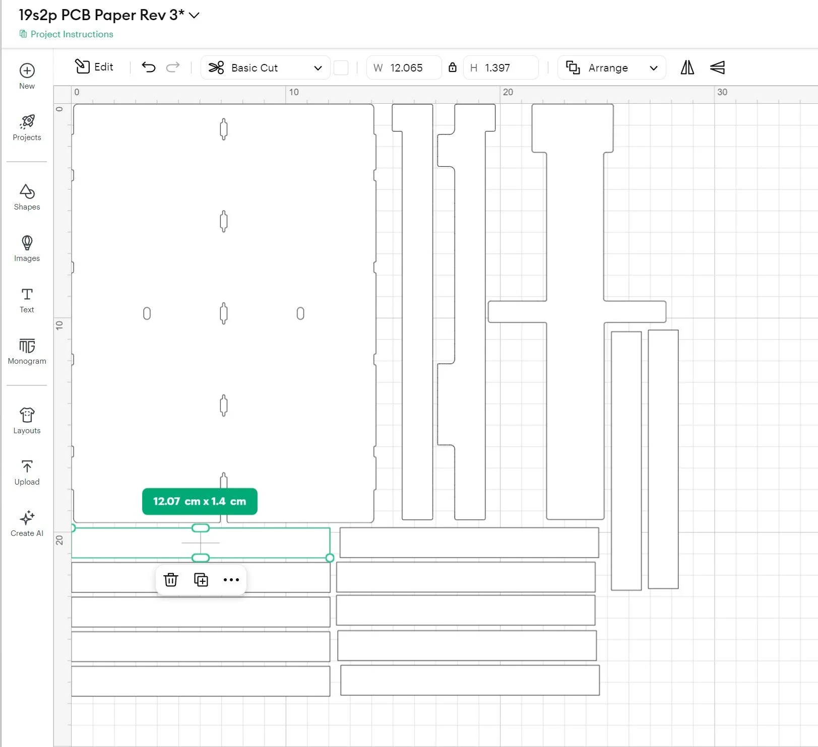
In addition to the PCB fish paper insulator shape, there are custom shapes to cut for the top of the PCB after installing it onto the battery pack. These paper shapes cover over and insulate the soldered terminals and taps from the nickel. I’ll include another image below with their sizing in Cricut Design Space, and hopefully that will help clarify their final sizing in a 2D plotter.
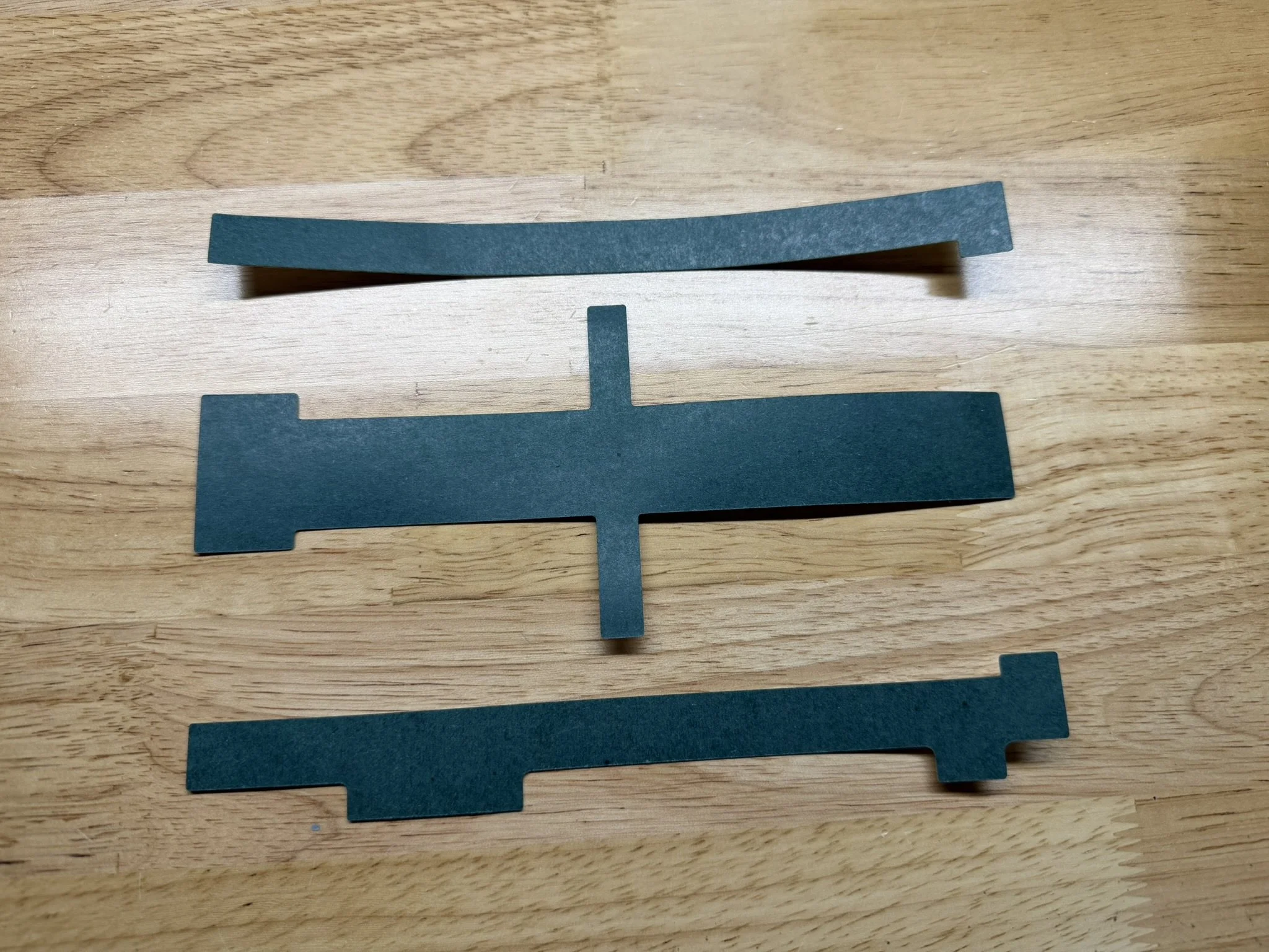
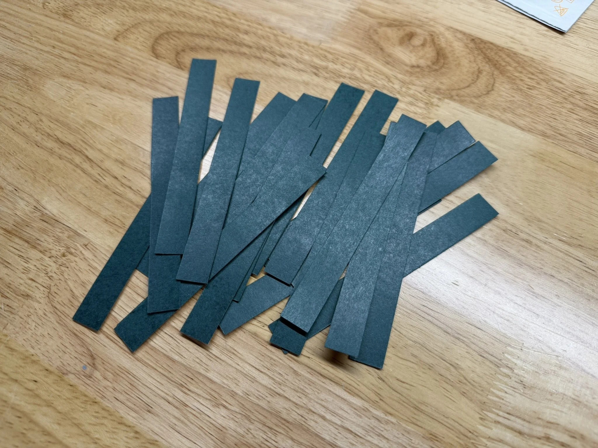
Lastly, there’s a large set of simple rectangular fish paper shapes that are used as cell insulators/spacers. There’s no vector file for this shape, since it’s a shape that can be drawn on any. These go around the parallel groups that are 2 cells wide. The images later in the article will illustrate that.
Custom Nickel Shapes
Also included in the files set, are the images needed for the custom nickel conductor shapes. Sourcing these is a bit more difficult than simply ordering PCBs from JLC. However, it’s essentially a matter of searching for a suitable manufacturer on Alibaba.com. There are a number of companies offering pure nickel battery conductors, that can take in the vector files in this included set, and cut them for you. Many existing battery builders in this hobby already have a manufacturer that they order from, and so it would probably be very easy to ask for suggestions within areas like the “Vesc Onewheel Builders” Facebook group or the “Vescify” Discord server.
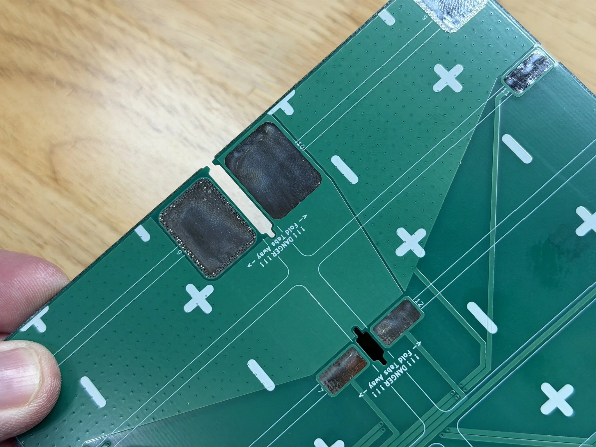
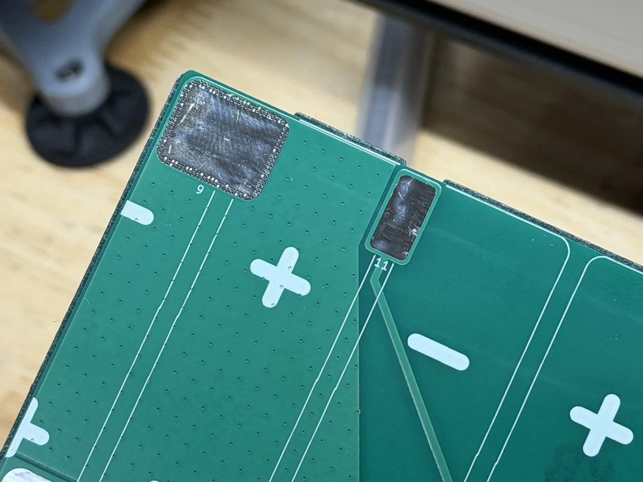
In the image below of some of the custom nickel shapes, you’ll notice that I scuffed/roughed up portions (with sandpaper). These are the parts that will connect to the PCB, and I’ve found that roughing the texture of nickel will help with the solder joints holding strong. In my opinion, it’s necessary.
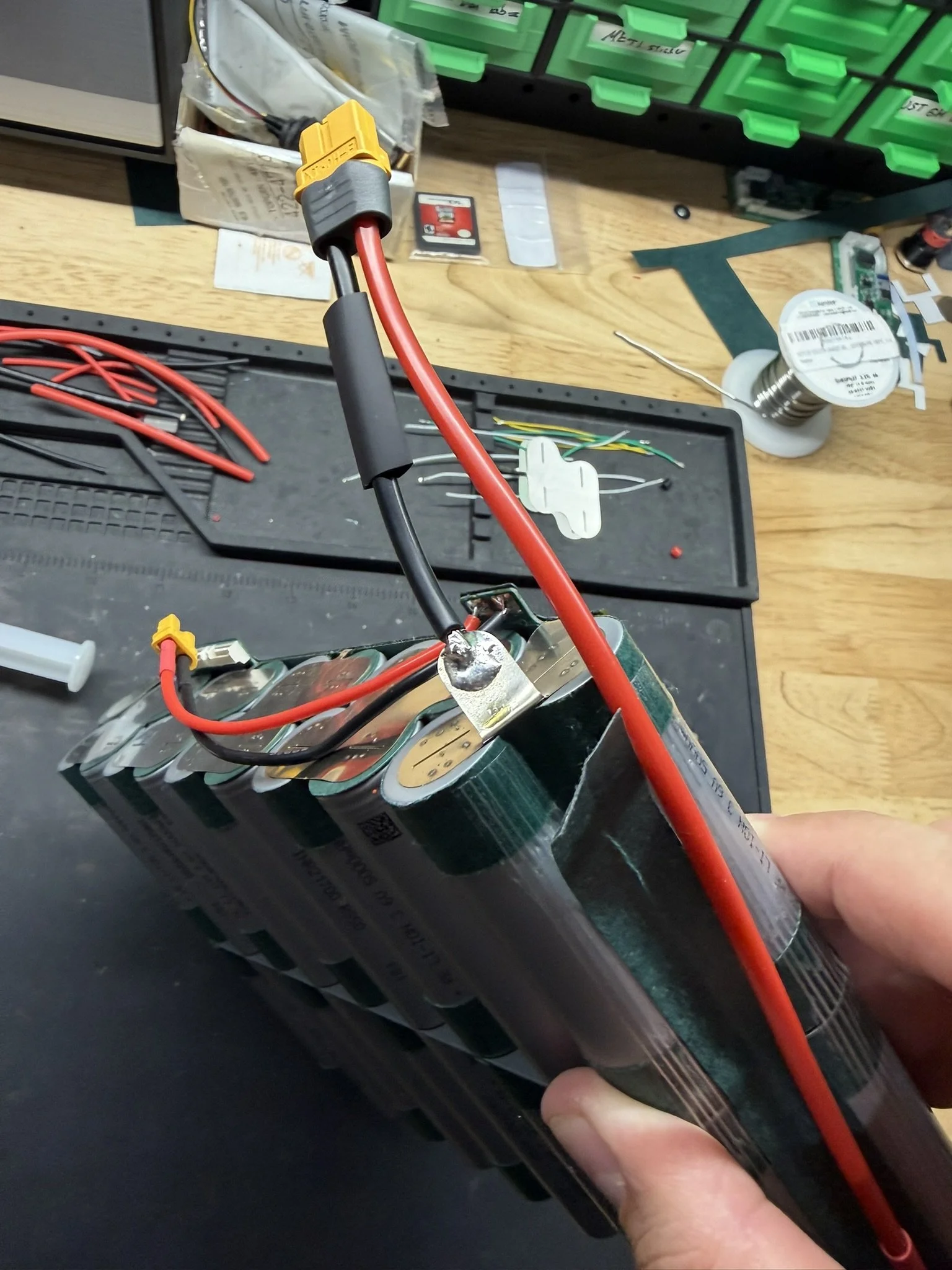
Wires
There are only 3 wiring sets needed for this pack design. One wiring set is the charging circuit, there’s also the discharge wiring set, and the last is the balance wiring harness. A diagram and technical drawing of the balance wiring harness is included in the file set. That specific wiring harness is designed to adapt the pack to an ENNOID XLITE V4 BMS. You could use that reference drawing to adapt the 19 cells to any BMS as needed.
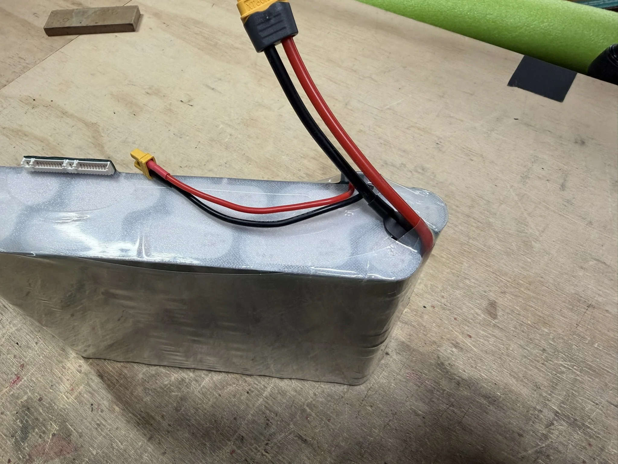
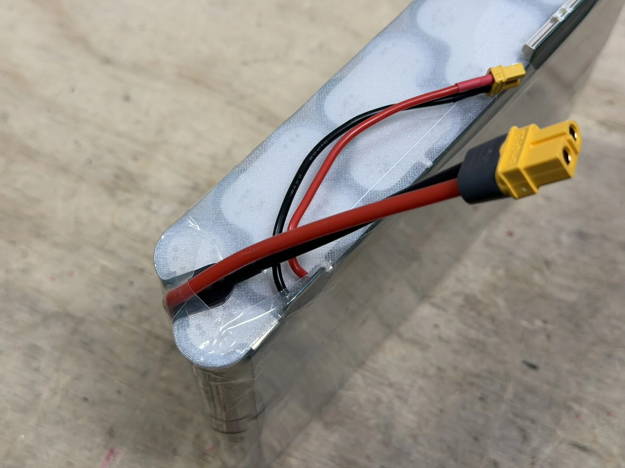
The charge circuit wiring is a simple XT30 connector with 18awg silicone wire. The negative (black) wire measures 100mm. The positive (red) wire measures 90mm.
The discharge circuit wiring is a simple XT60 connector with 13awg (yes, I use 13awg, but you can probably use 12awg) silicone wire. The negative (black) wire measures 80mm. The positive (red) wire measures 225mm.
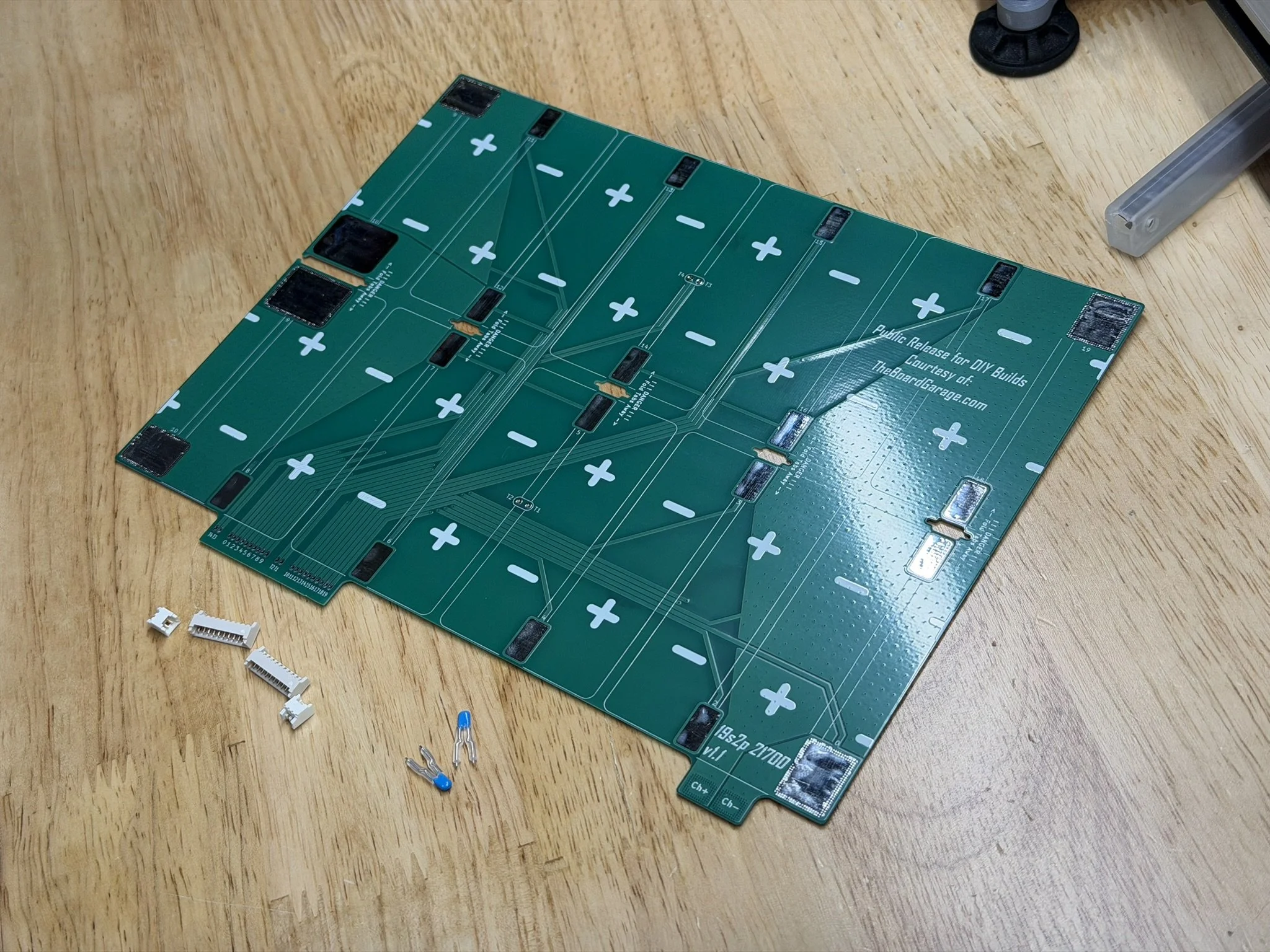
Part 3 - PCB Preparation
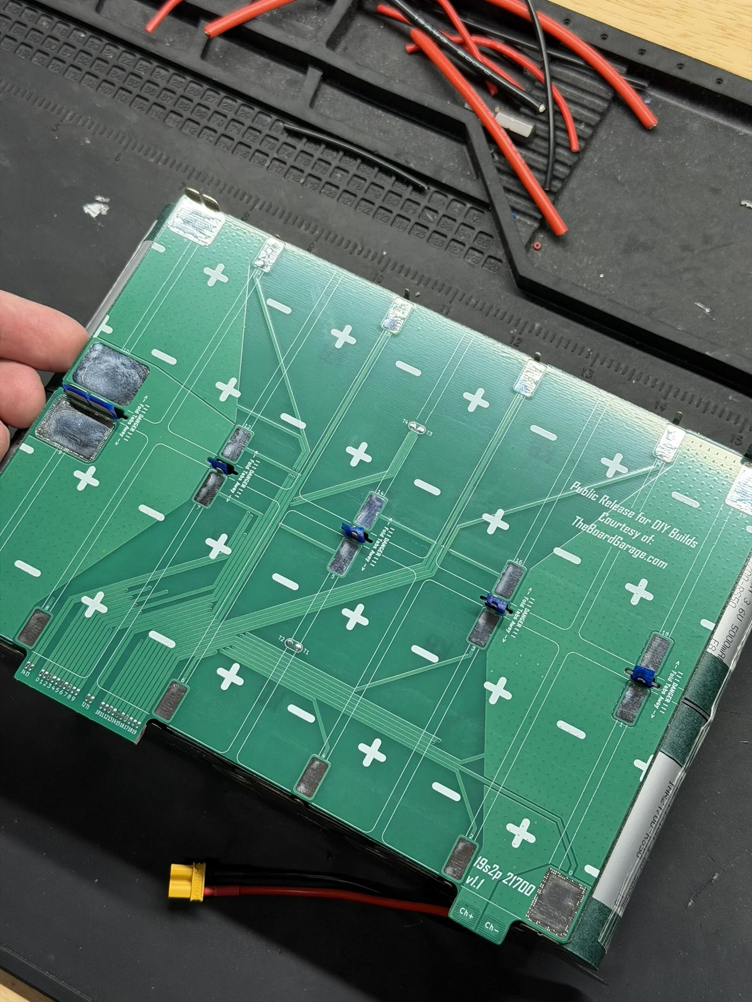
Obviously, the PCBs arrive unpopulated. And so assembly of the parts on the PCB is required before it can be installed onto the battery pack. There are a few steps, and the first ones are particularly important to get right.
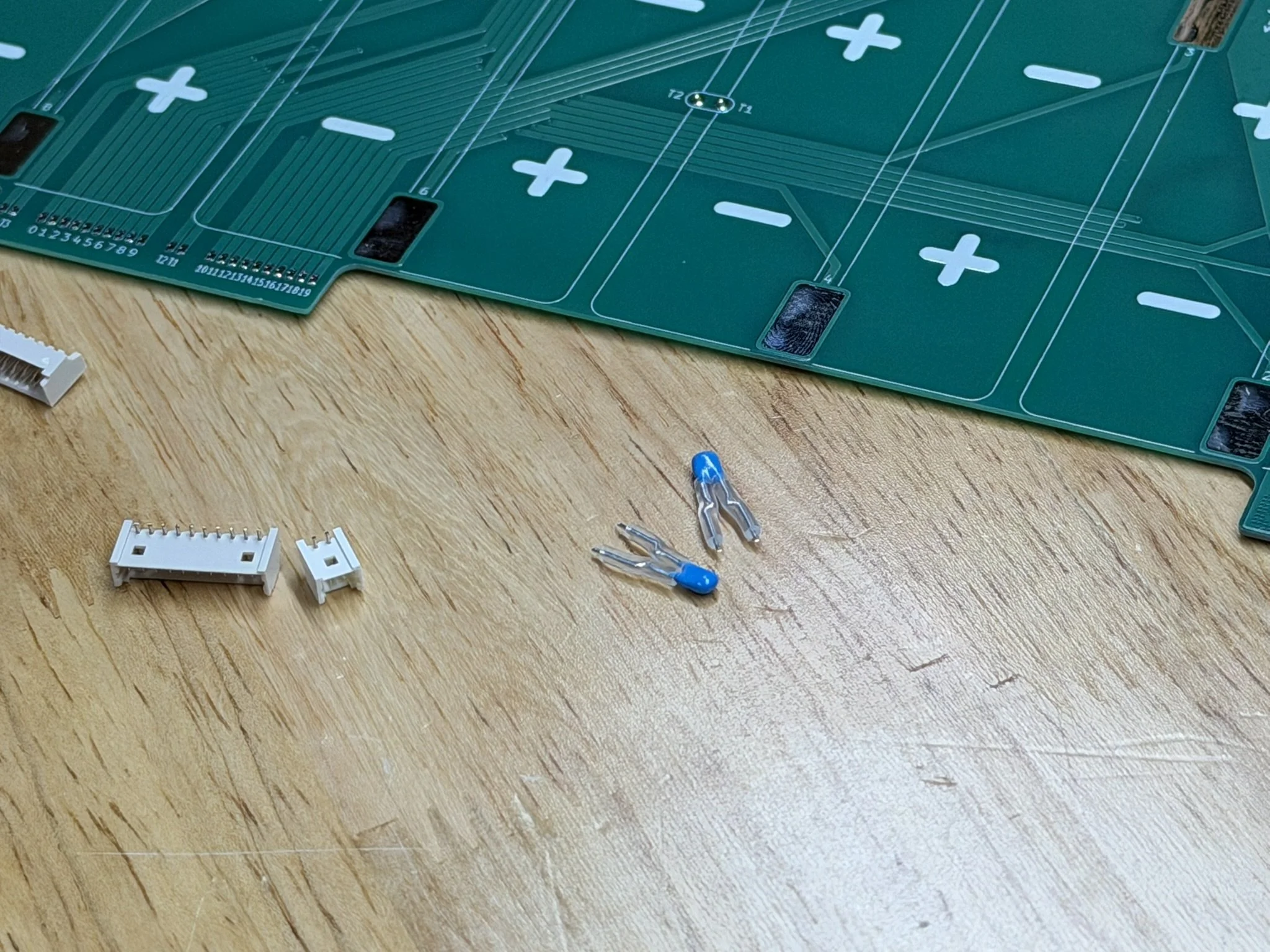
Molex PicoBlade Connectors
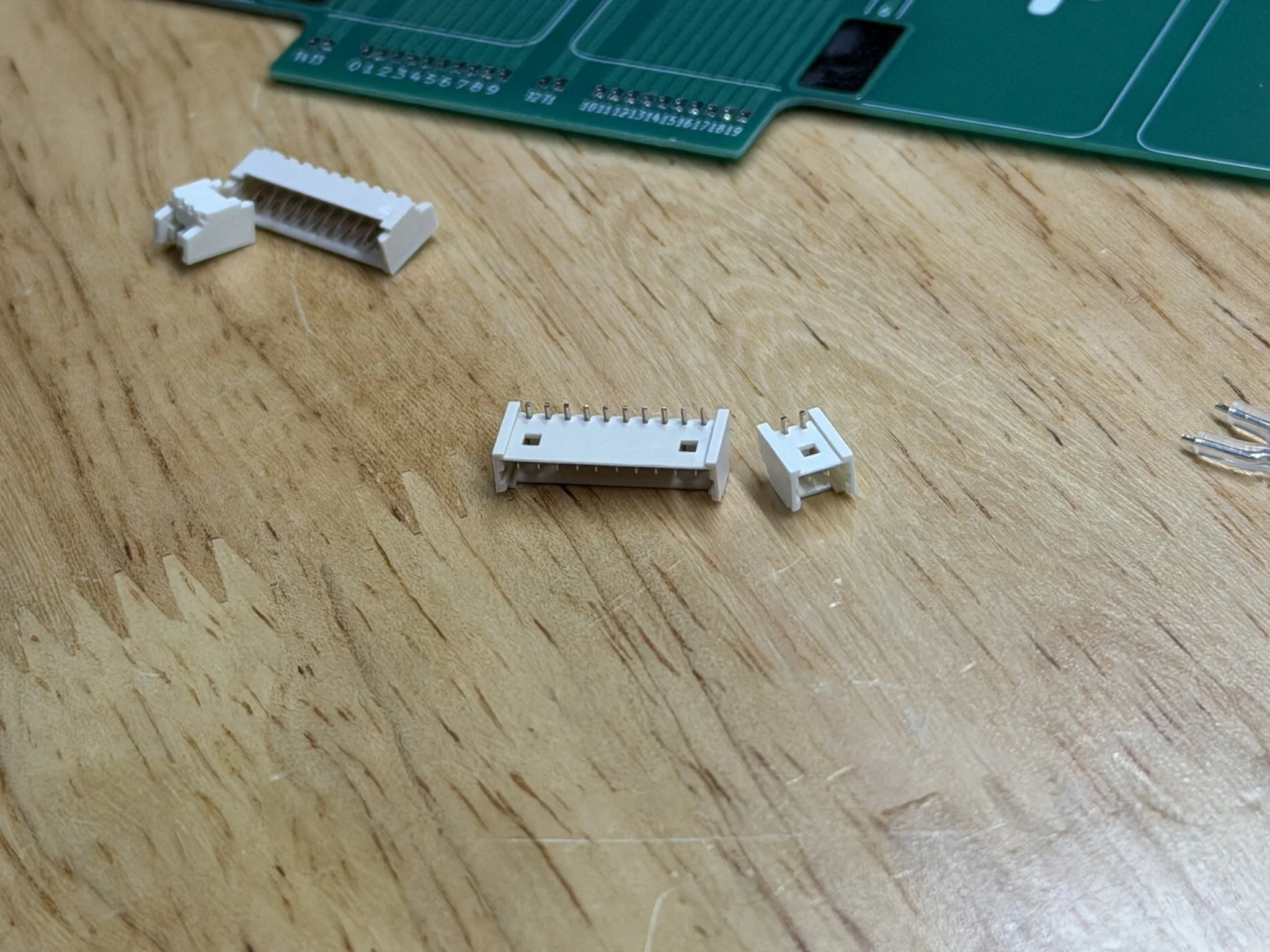
The balance connections on this battery design are handled by a Molex PicoBlade connector set. There are 2× 10-pin headers for the cell taps, and 2× 2-pin headers for the temperature sensors (which also get installed onto the PCB).
DO NOTE THAT THE HEADER HAS PINS THAT ARE TOO LONG. THEY NEED TO BE SHORTENED.
The way I shorten the header solder pins is by cutting them down with precision flush cutters. What I aim for is to have the ends of the pins land SLIGHTLY BELOW the top surface of the PCB. This keeps any extra sharps with active voltages away from the top surface.
PCB Insulator Fish Paper
As mentioned in the video, and the section above on fish paper, THIS PART IS CRITICAL.
I install the fish paper AFTER soldering on the Molex PicoBlade headers. This way, I can fully clean the PCB with the above linked flux remover, as well as a clean wipe with isopropyl alcohol.
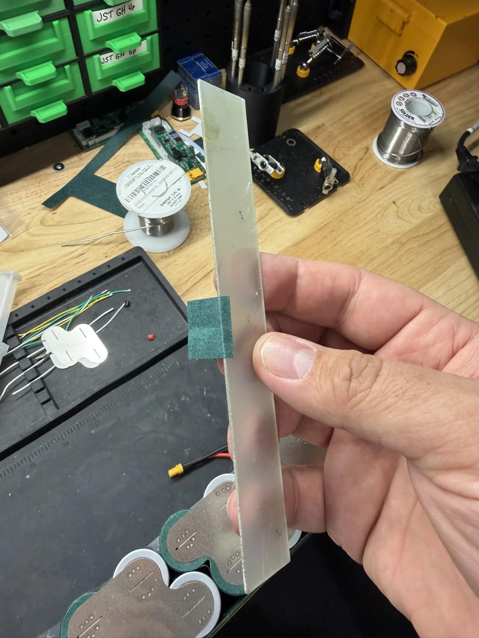
After that, I use the printed alignment jig to do a dry fit, and then install the fish paper insulator. This part is tricky, so I start from the center, and then press the adhesive outward.


Temperature Sensors
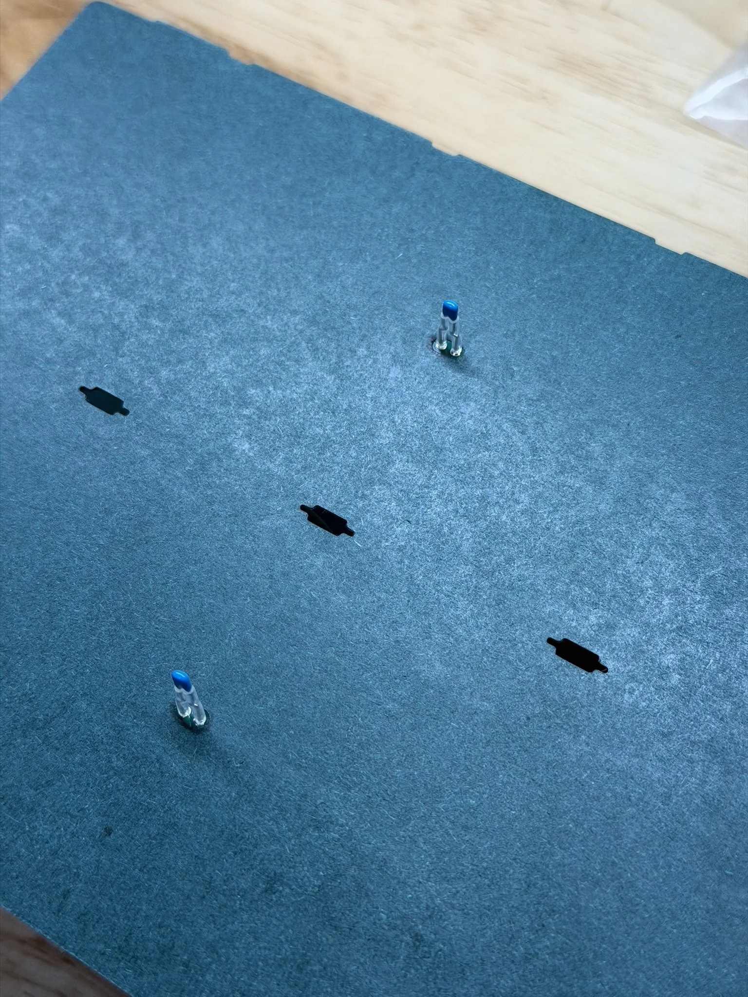
The above linked temperature sensors (thermistors) are what I have always used for battery packs that I pair with an ENNOID XLITE BMS. These in particular have longer leads, and so I trim them to fit. They end up about 10mm/1cm in length. Also, I add a small length of the above linked silicone tubing around those leads to insulate them from any cell surface they come into contact with while the PCB gets installed against the pack.
After that, once the fish paper is applied, the leads are soldered into the 2 locations in the center of the PCB.
Just like the Molex PicoBlade headers, it’s VERY IMPORTANT for the leads to not protrude up beyond the PCB top surface. The solder joint should be flush and smooth.

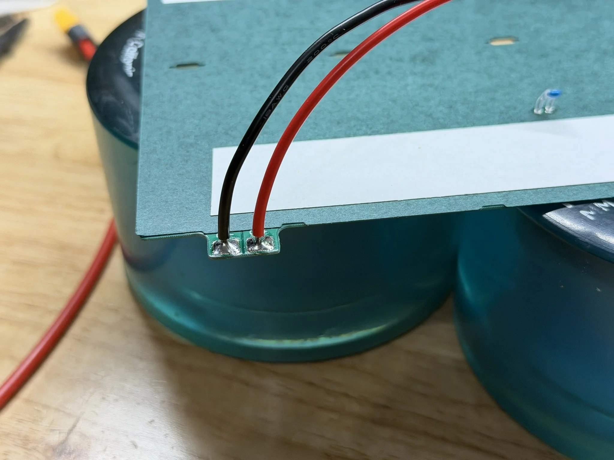
XT30 Charge Connector
There is a designated set of solder pads to install the XT30 connector set. The polarity is marked on the PCB.
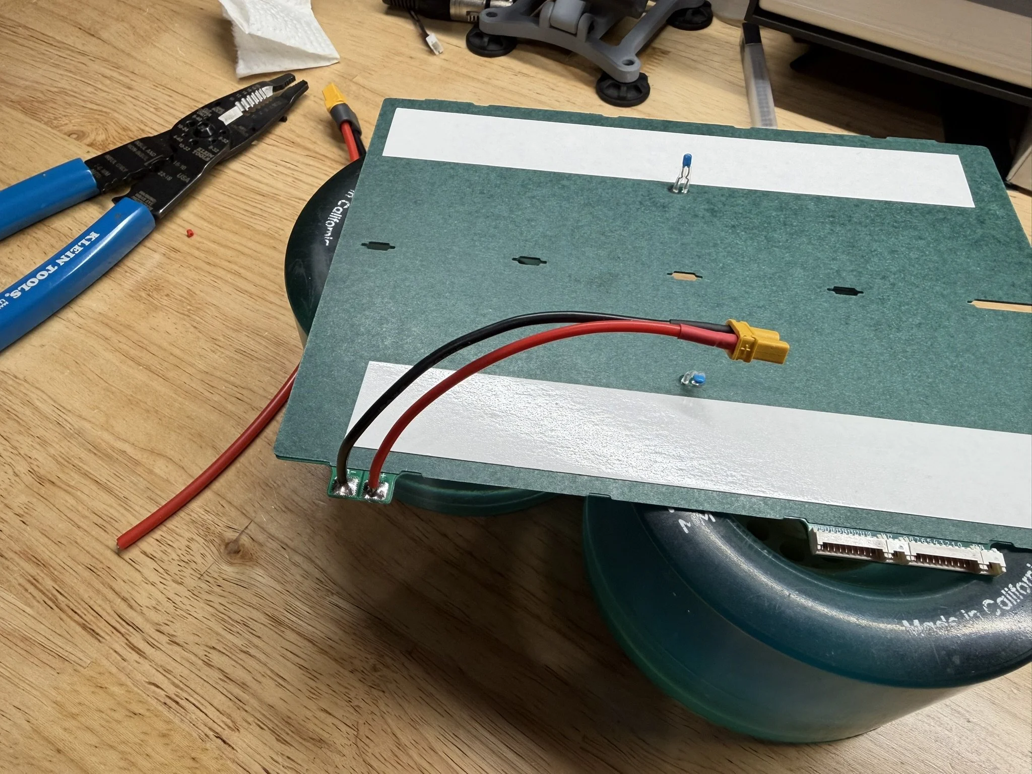
Adhesive Tape
The underside of the PCB gets 2 pieces of double sided adhesive tape, for adhering/mounting it to the battery pack. In this build, it’s placed on the outer sides of the temperature sensors. The tape is linked above in the Incidental Parts list. This is what’s recommended due to its strength and thinness.
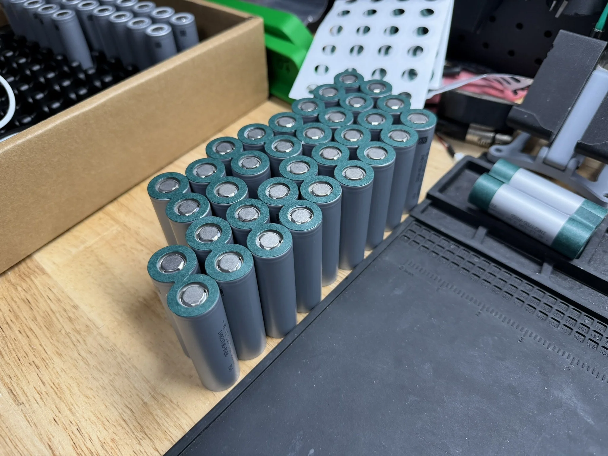
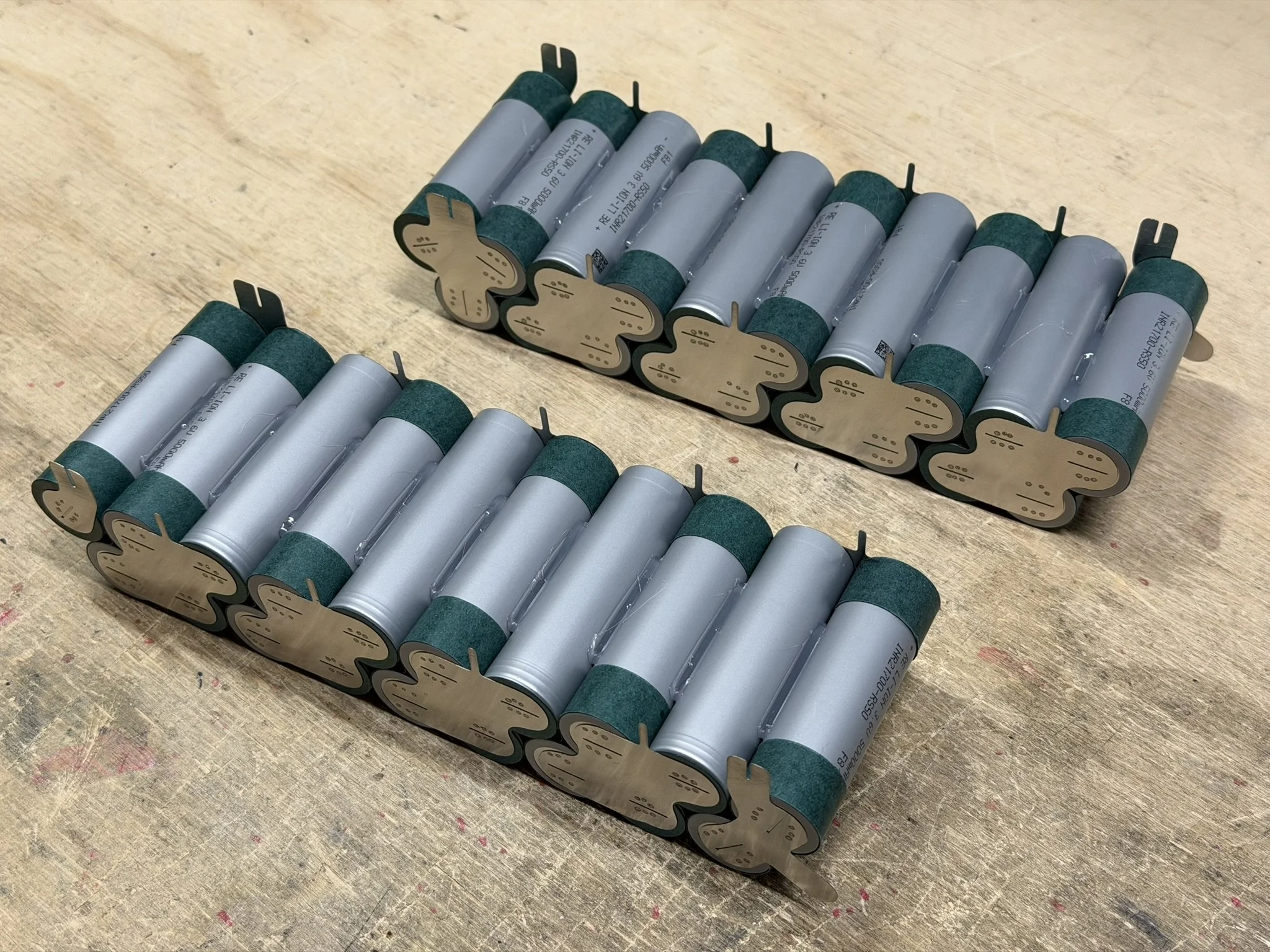
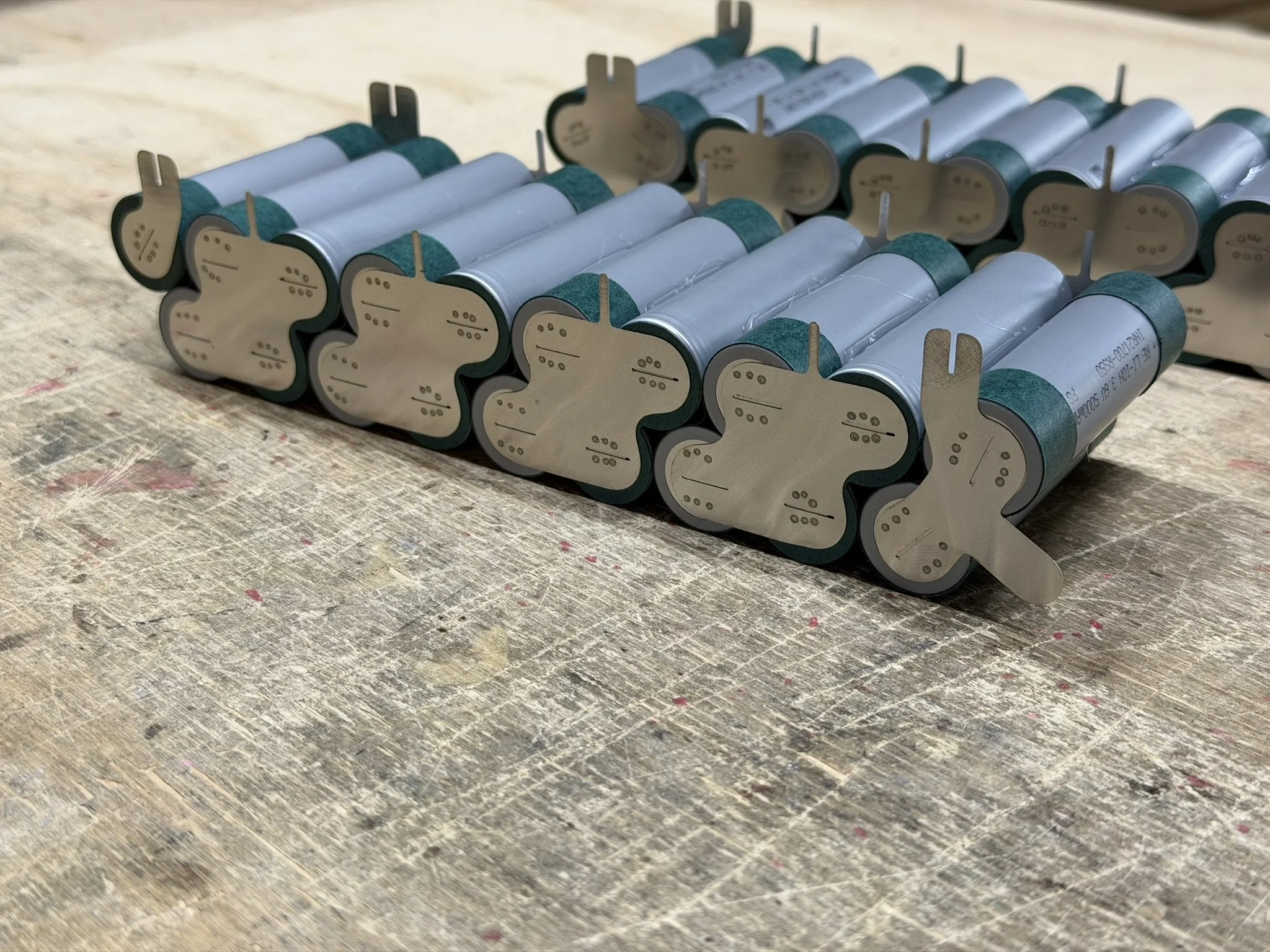
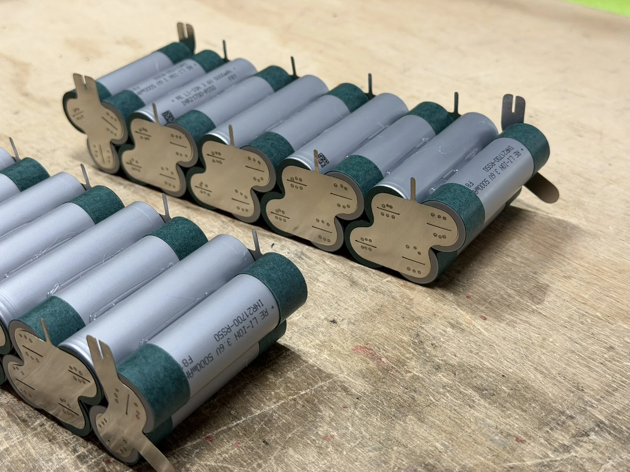
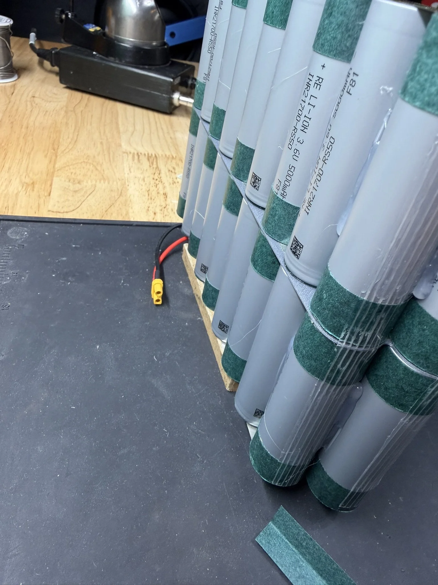
Part 4 - Cell Brick Glue Up
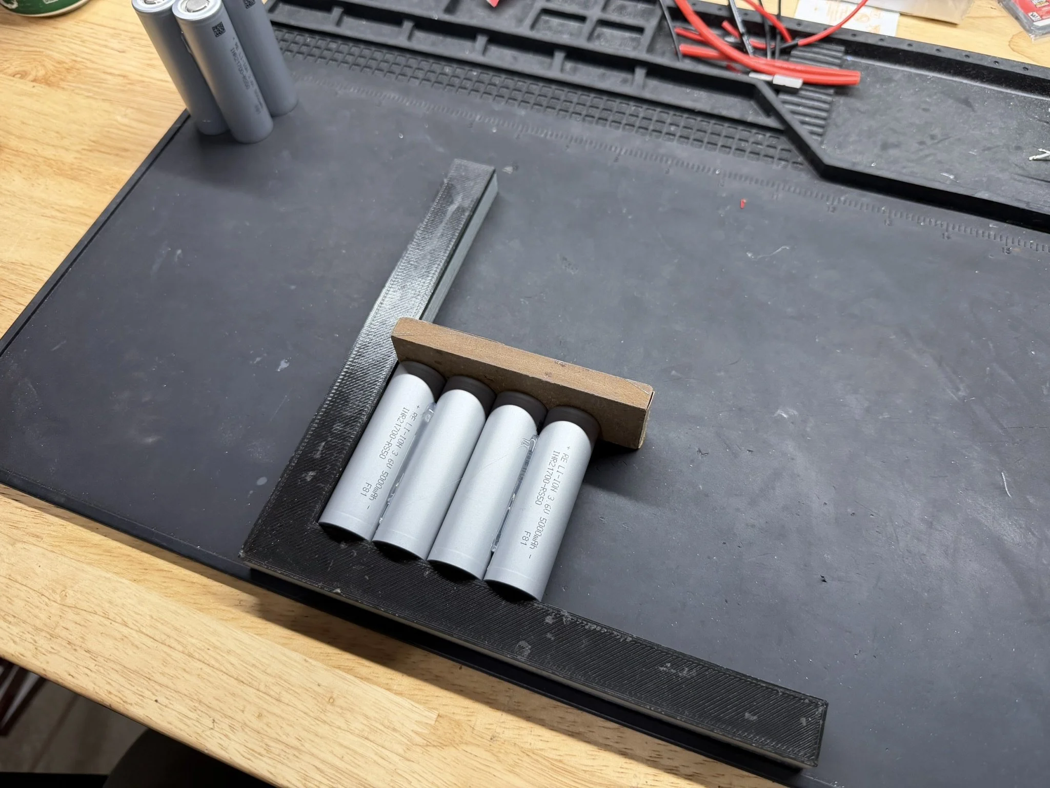
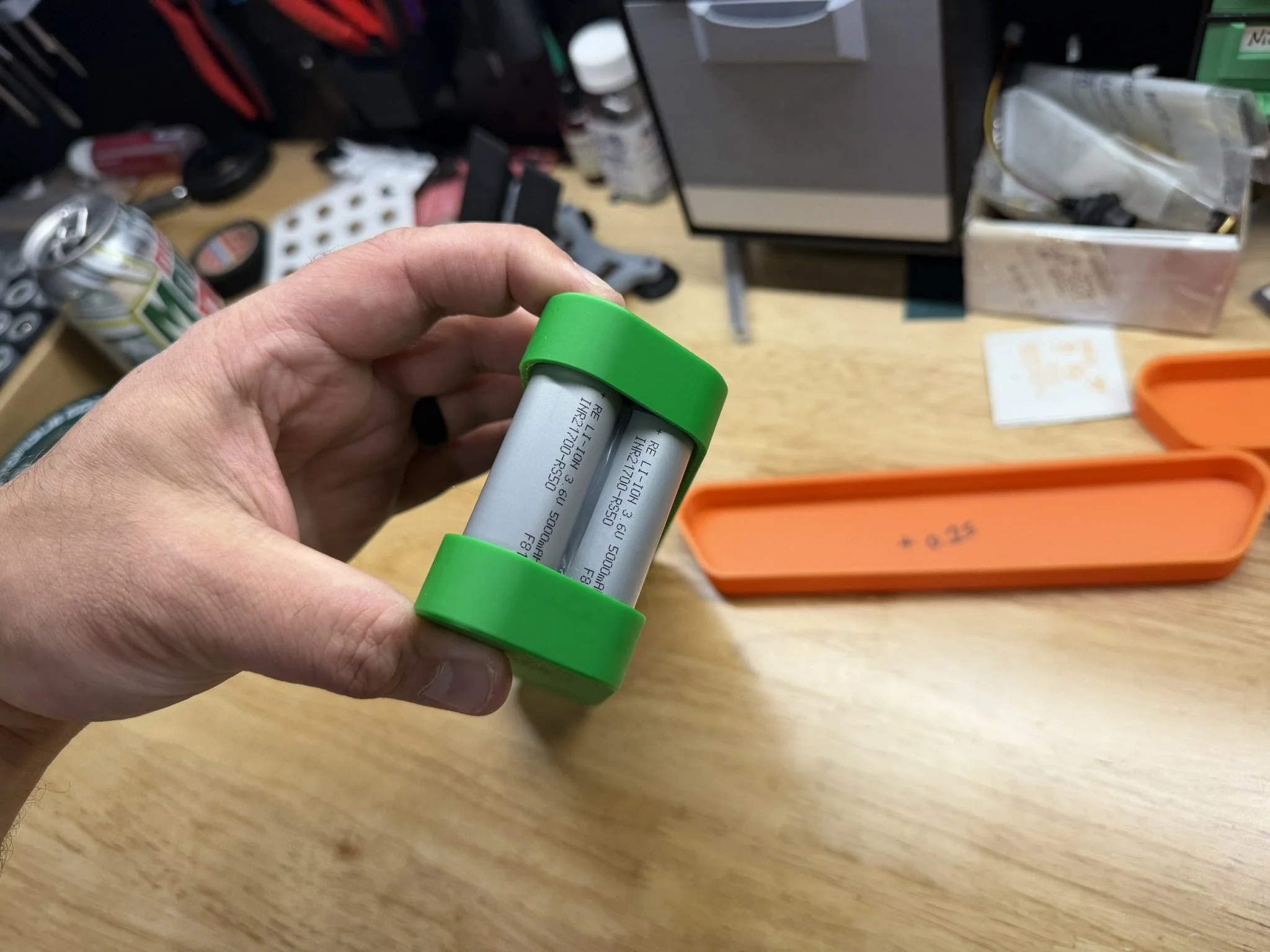
The cell brick itself is mostly conventional. If you have seen an 18s2p staggered cell brick, this is not too far off from that. The first step is to glue together the 2-cells-wide parallel group. These go side by side, same orientation. The cells get glued on both sides of the 2-cell group, and what I’ve done is make the full group of cells altogether, and then lay them down while adding the cell insulator top rings.
The gluing order (for me) is as follows:
Glue 2 cells together side by side (2p group).
Repeat until all groups are collected.
Add 2x single cells for the split shoulder group.
Take each glued 2p group, add insulator rings, set glue-side-down on bench.
Glue the other side of each 2p group.
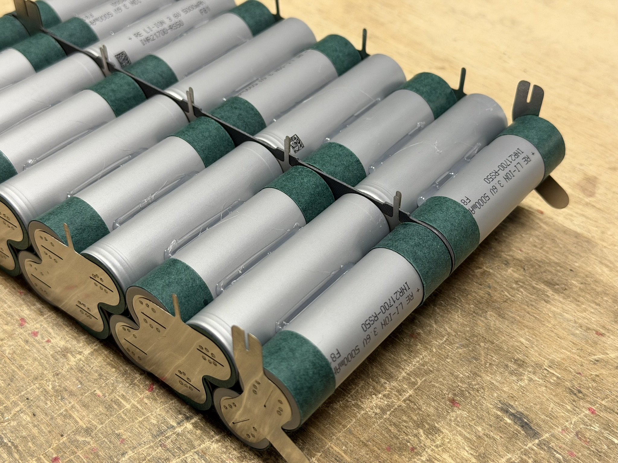
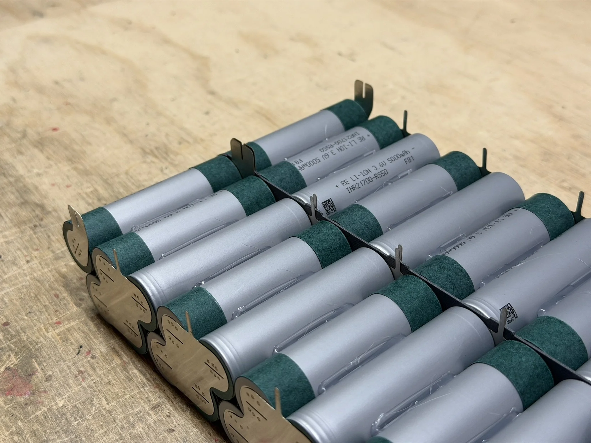
After each 2p group is together and the insulator rings are added, they get the fish paper cell spacers/insulators. Every other group has this added, since only one layer of fish paper is needed between cell groups.
The single cell for each pack half, gets a half of a fish paper strip. I just cut one strip in half, and add it so that the gaps line up.
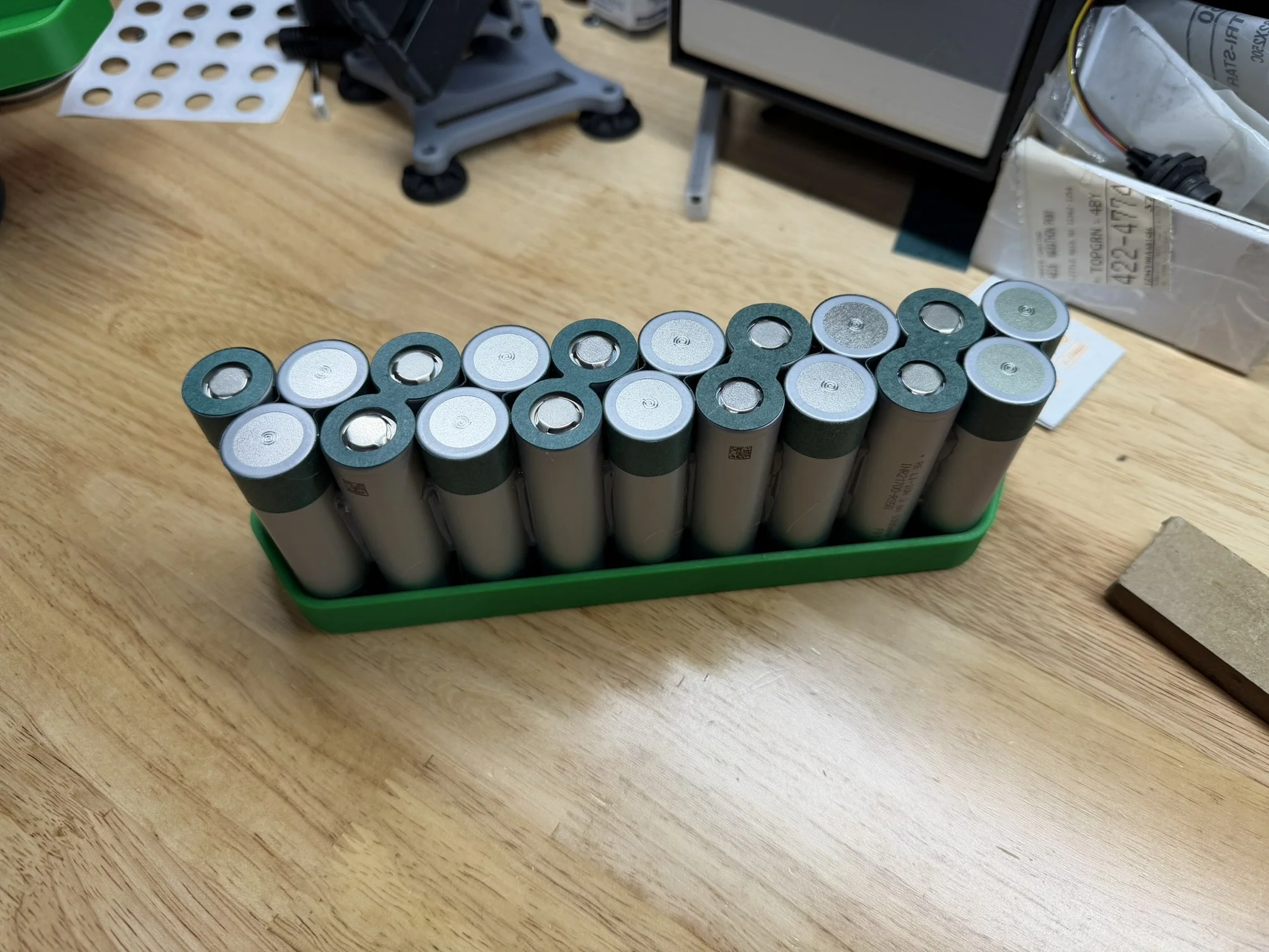
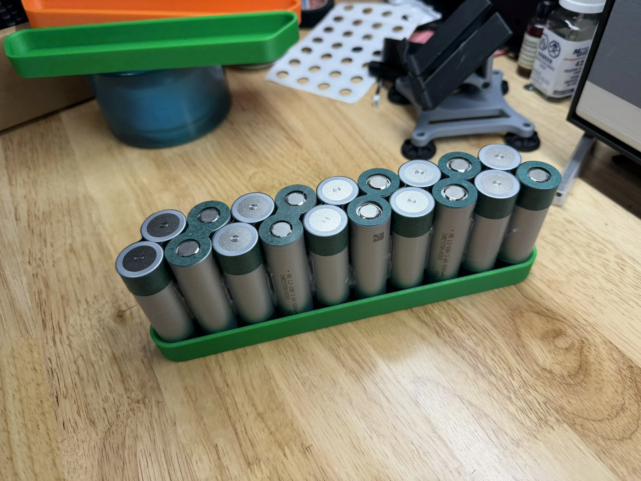
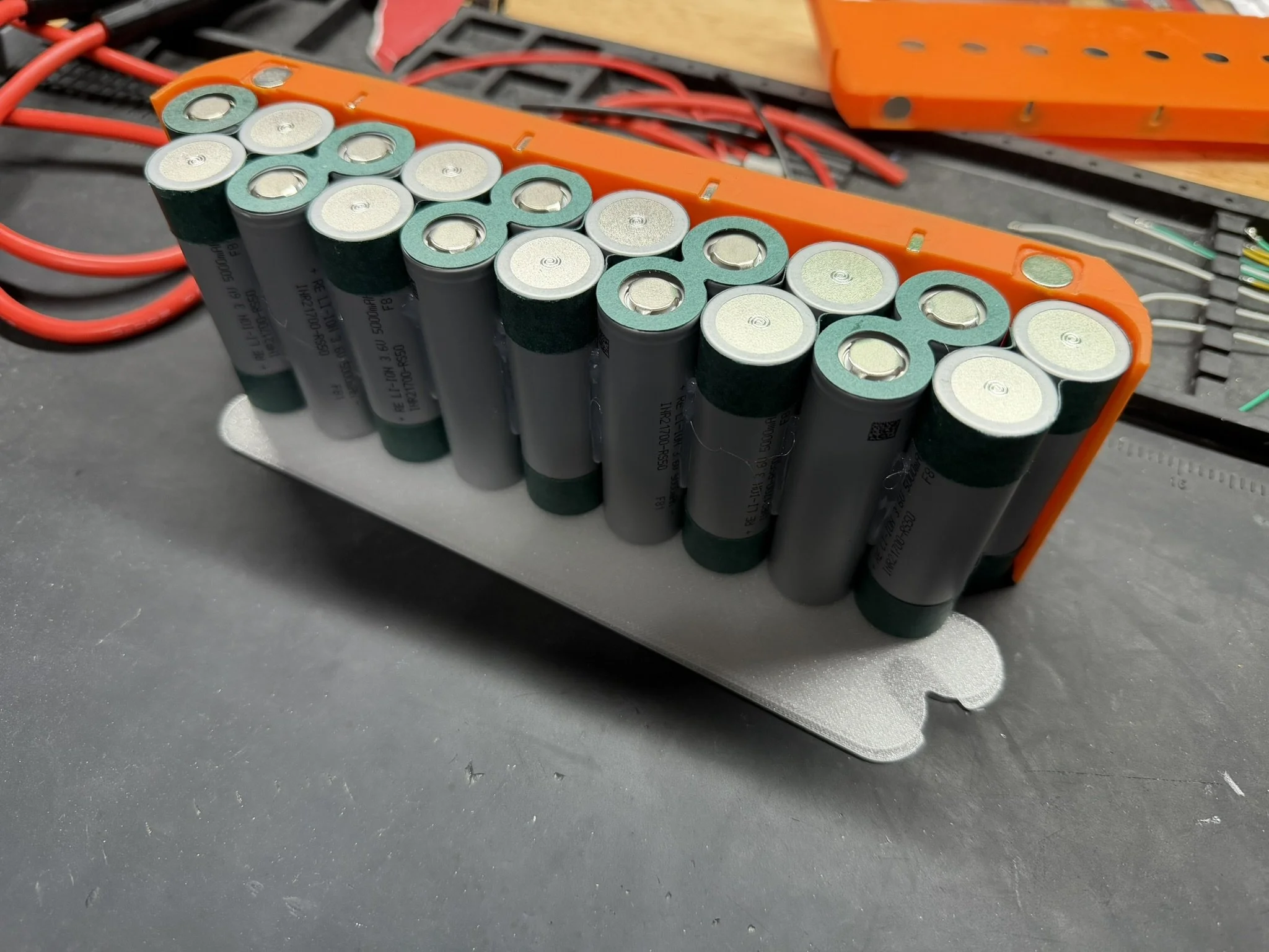
Once all groups are papered, they go into the glue jig in the orientation shown in the images below. Each pack half has the same cell orientation, even though the nickel gets welded on differently for each half. Note that the single cell in the brick is oriented so that the fish paper contacts the paper of the other cell group. This mainly keeps the paper in place. When filling the glue jig, I usually insert one of the papered groups in the middle last. This helps get the outer groups in without damaging the fish paper on the shoulder of the cells.
After that, I glue all around the entire brick.
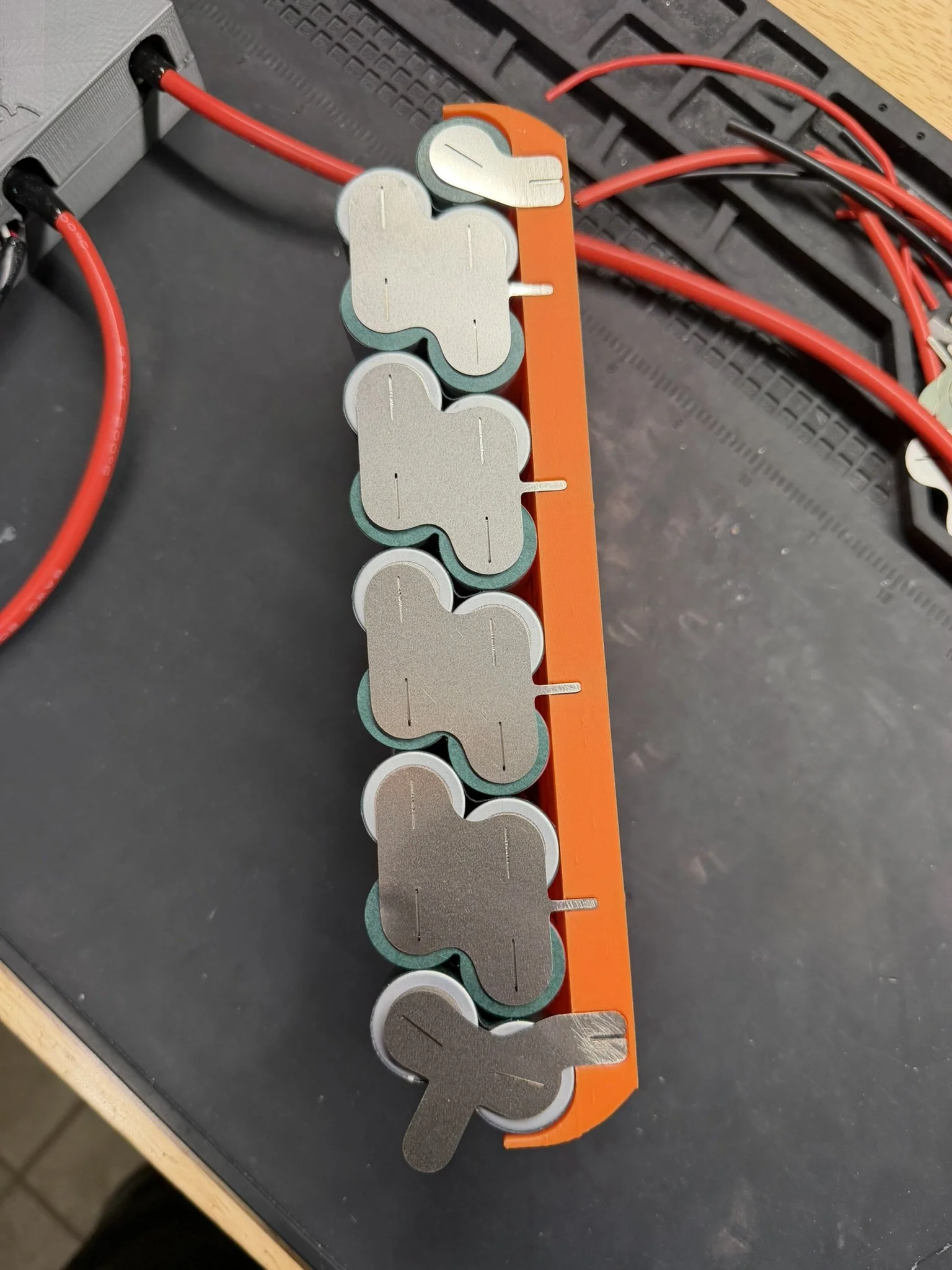
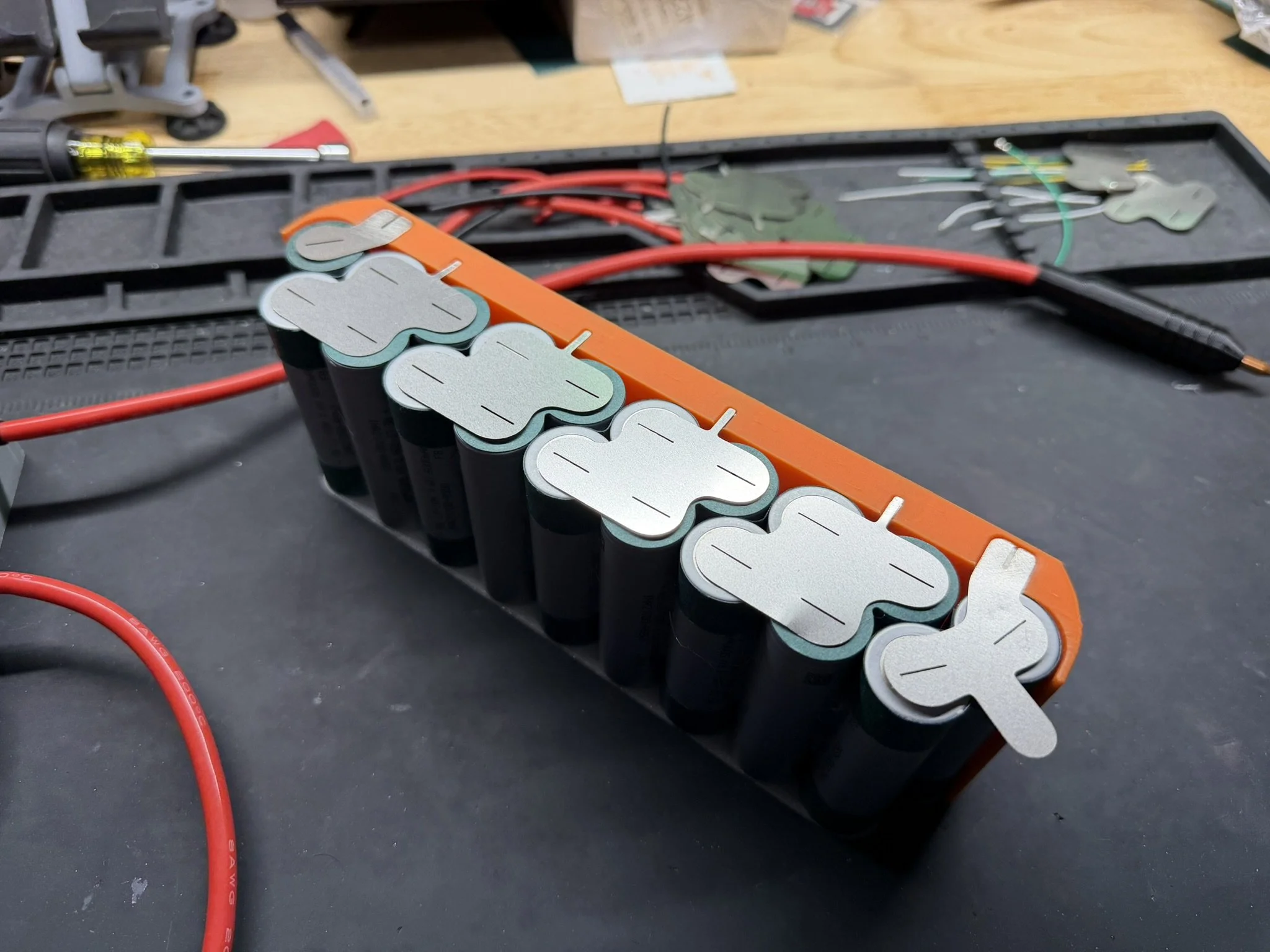
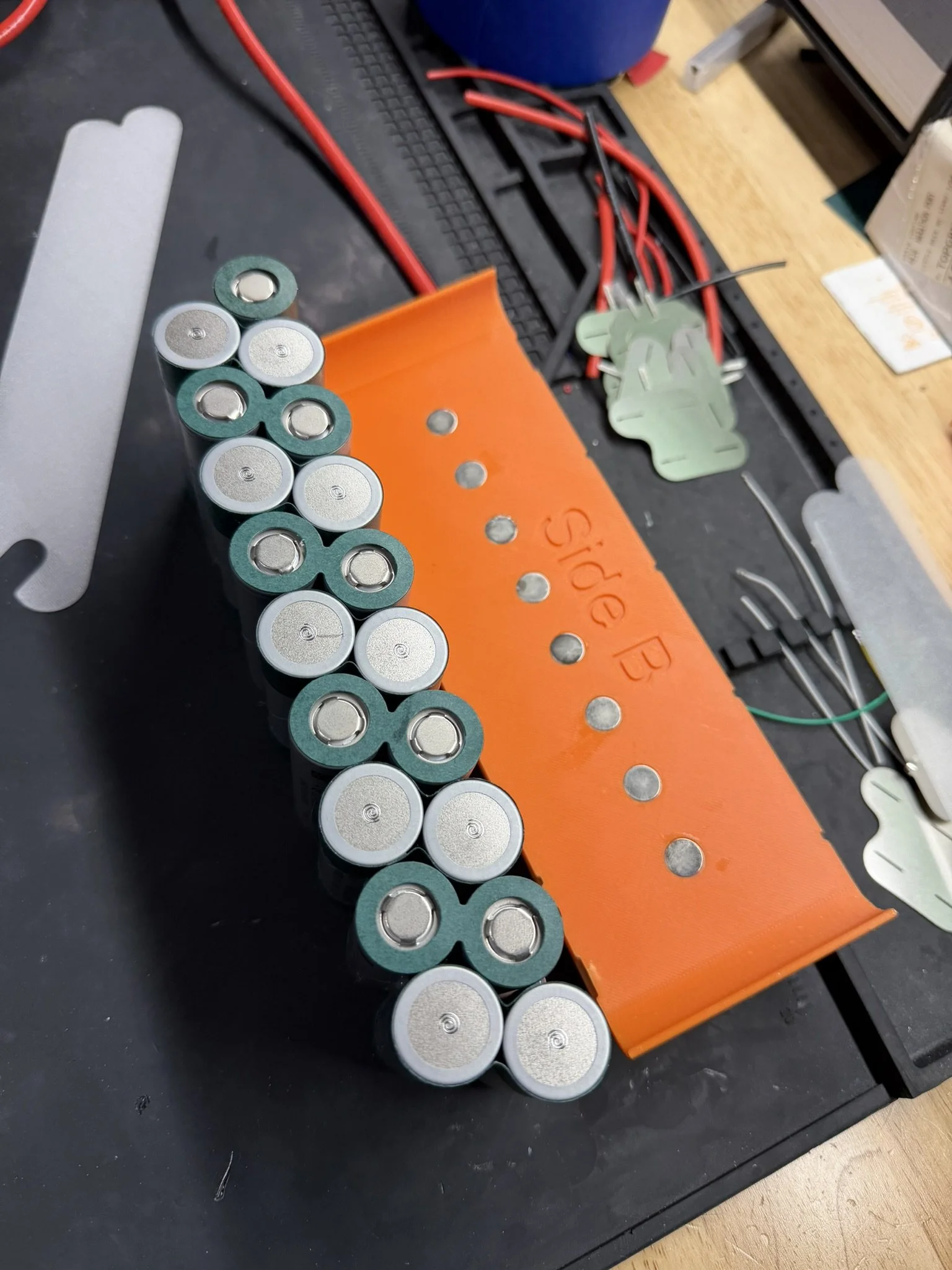
Part 5 - Welding The Nickel Conductors
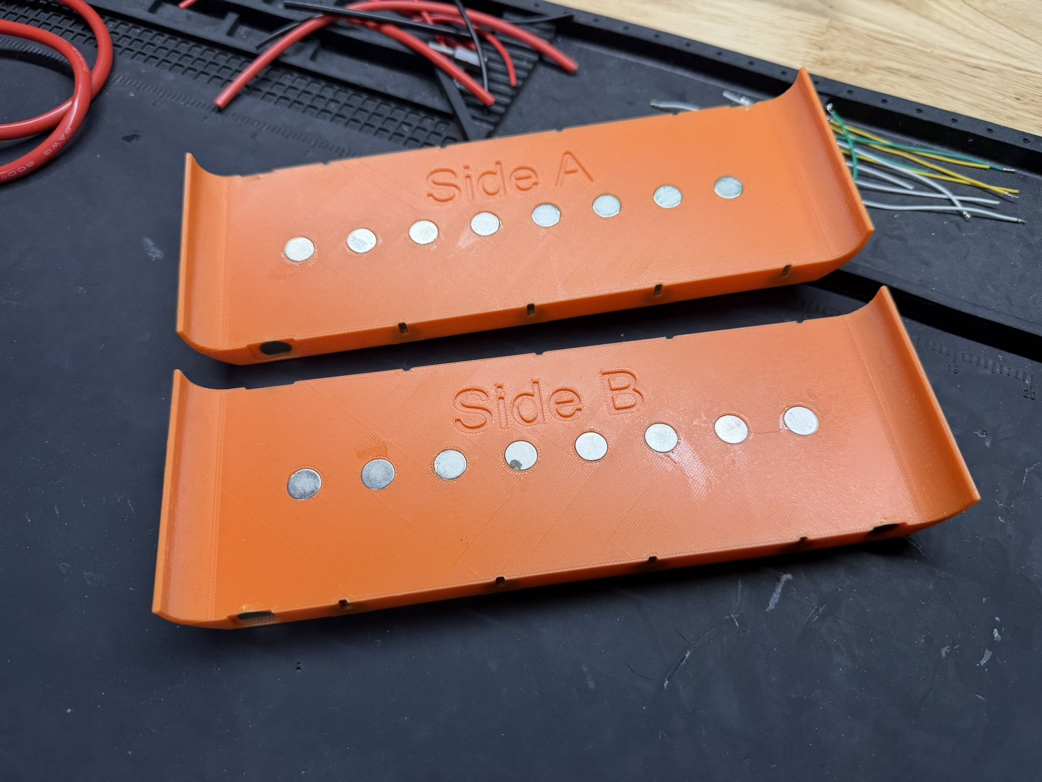
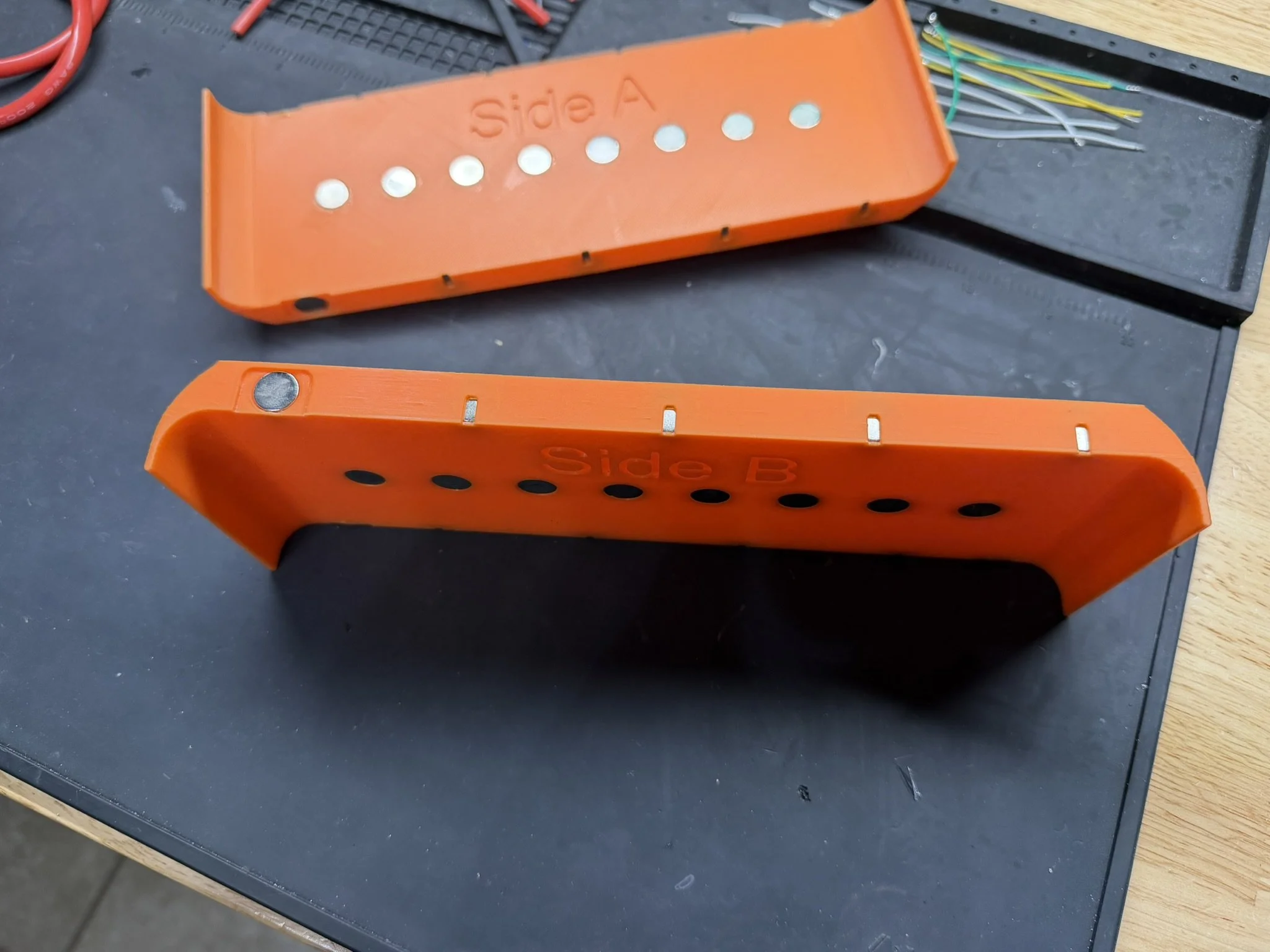
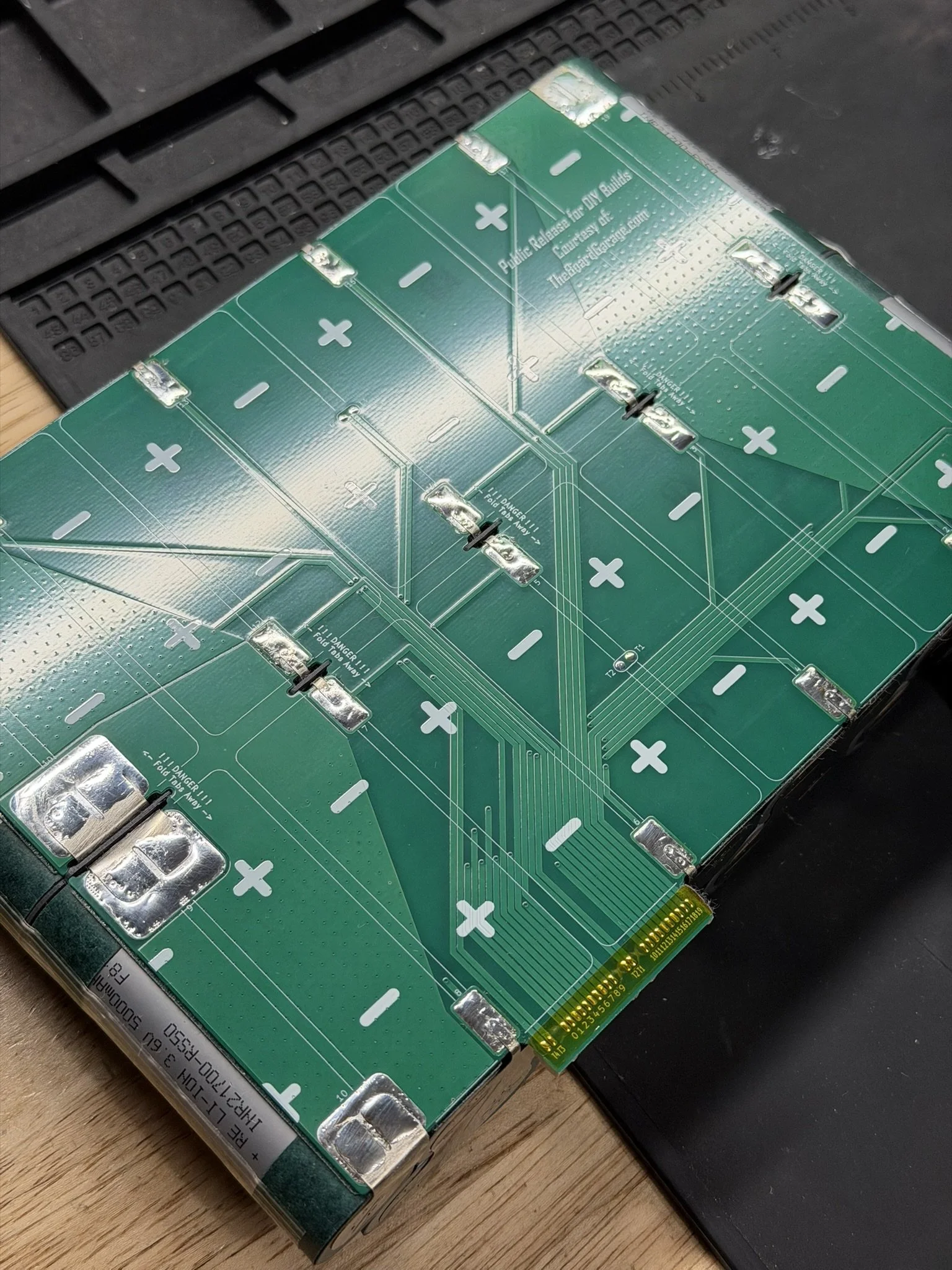
Like other parts of the build, this is a fairly standard pack building process. There are included welding jigs in the file set, and after printing those, I install the 10mm magnets linked above in the parts section. They help to hold the nickel in place, but they aren’t dead strong clamps. Standard safety procedures should be in place, such as welding one piece at a time, and insulating (taping off) adjacent cells and nickel while welding.
Each jig is labeled “Side A” and “Side B”. Side A is closest to the tail, Side B is closest to the nose. The orientation of the pack halves, nickel, and marking are from a “back to front” perspective. Make sure to understand your bearings before committing to permanent joints.

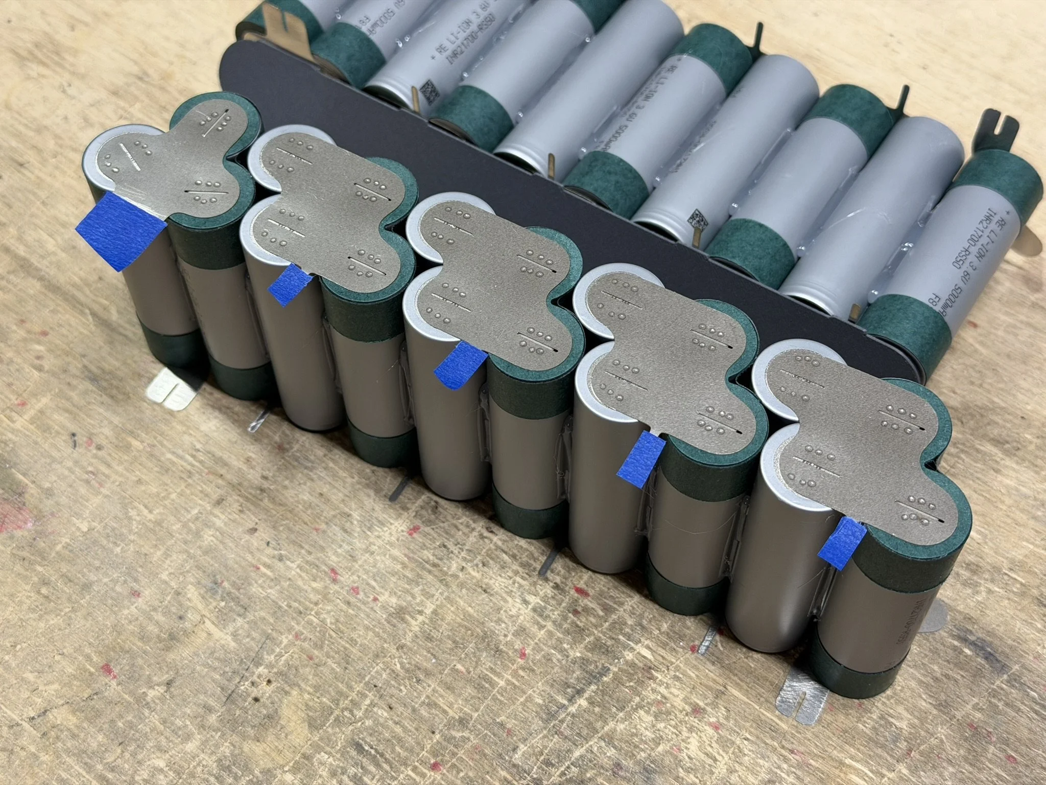
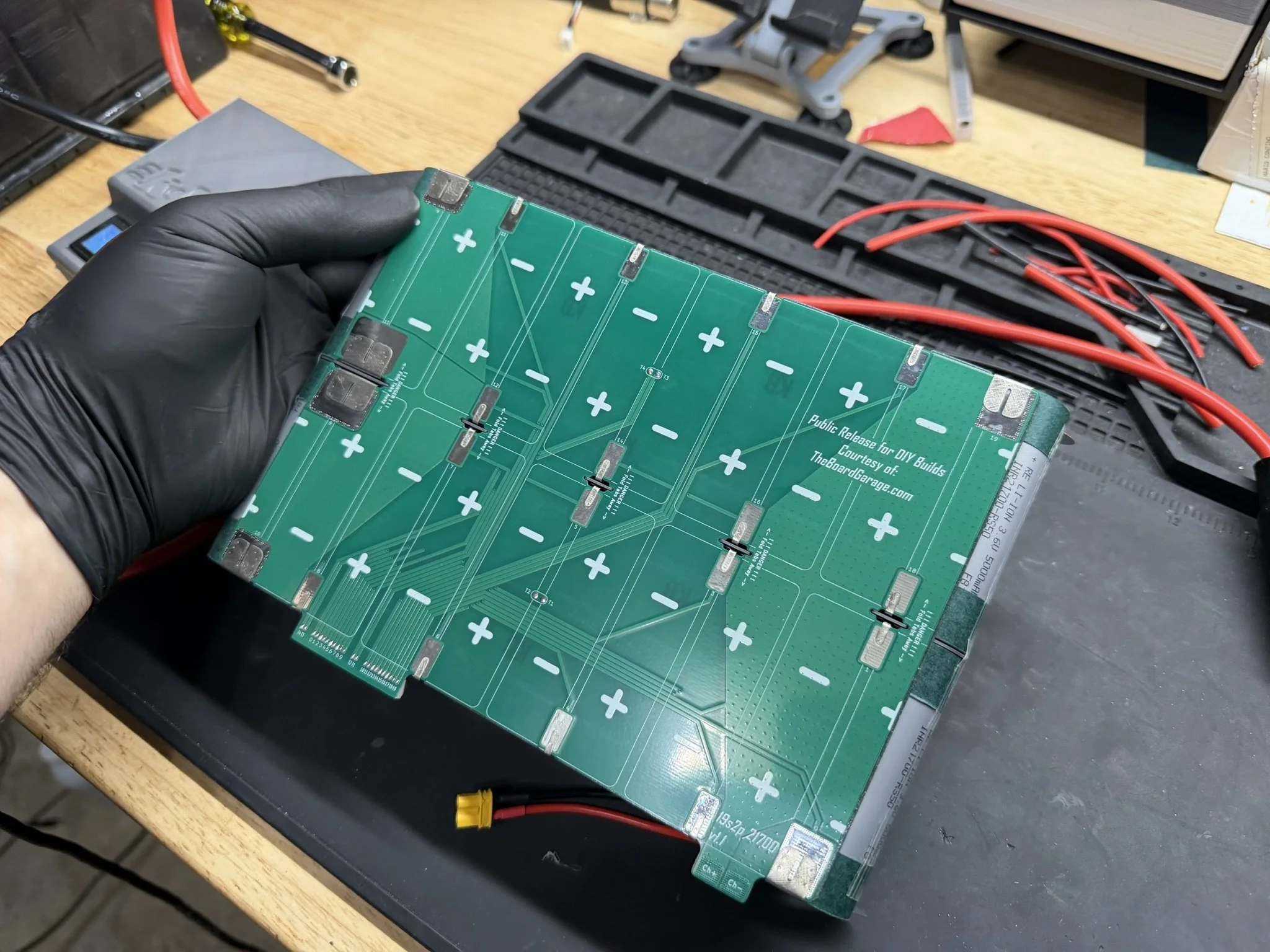
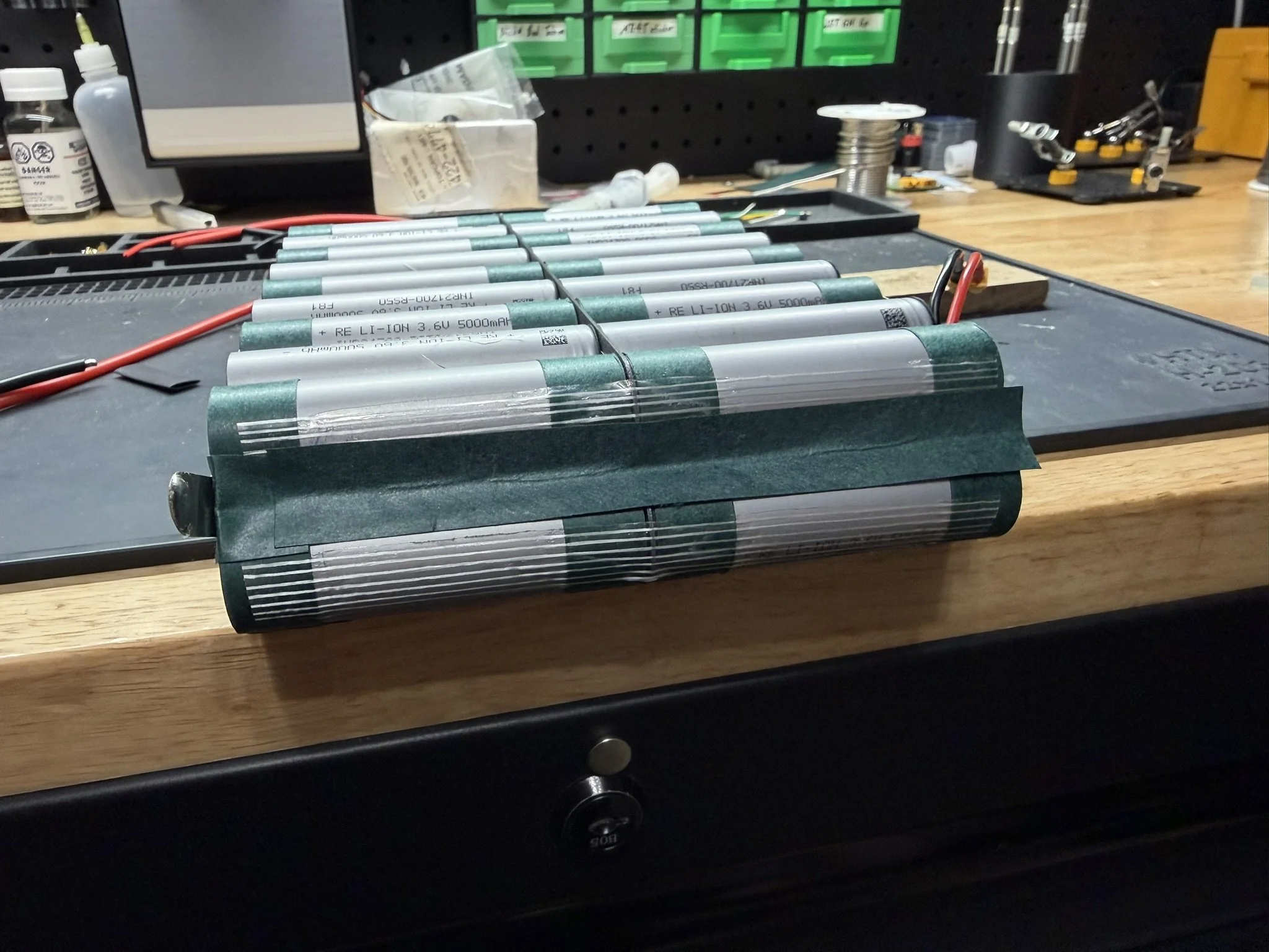
Part 6 - Assembling The Pack
Cell Brick
When the pack halves come together, I add some blue masking tape pieces to the nickel balance tabs, just as a precautious for installing the PCB. The printed center insulator/divider goes between halves, and has only one orientation. There are keying shapes on the top of the divider, and the wide one aligns with the wider nickel tabs.
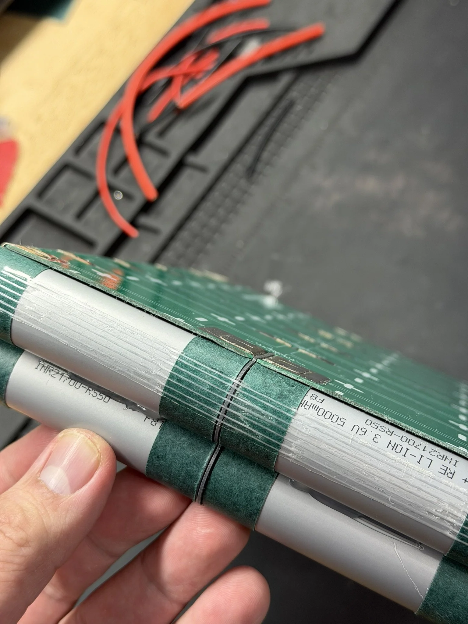
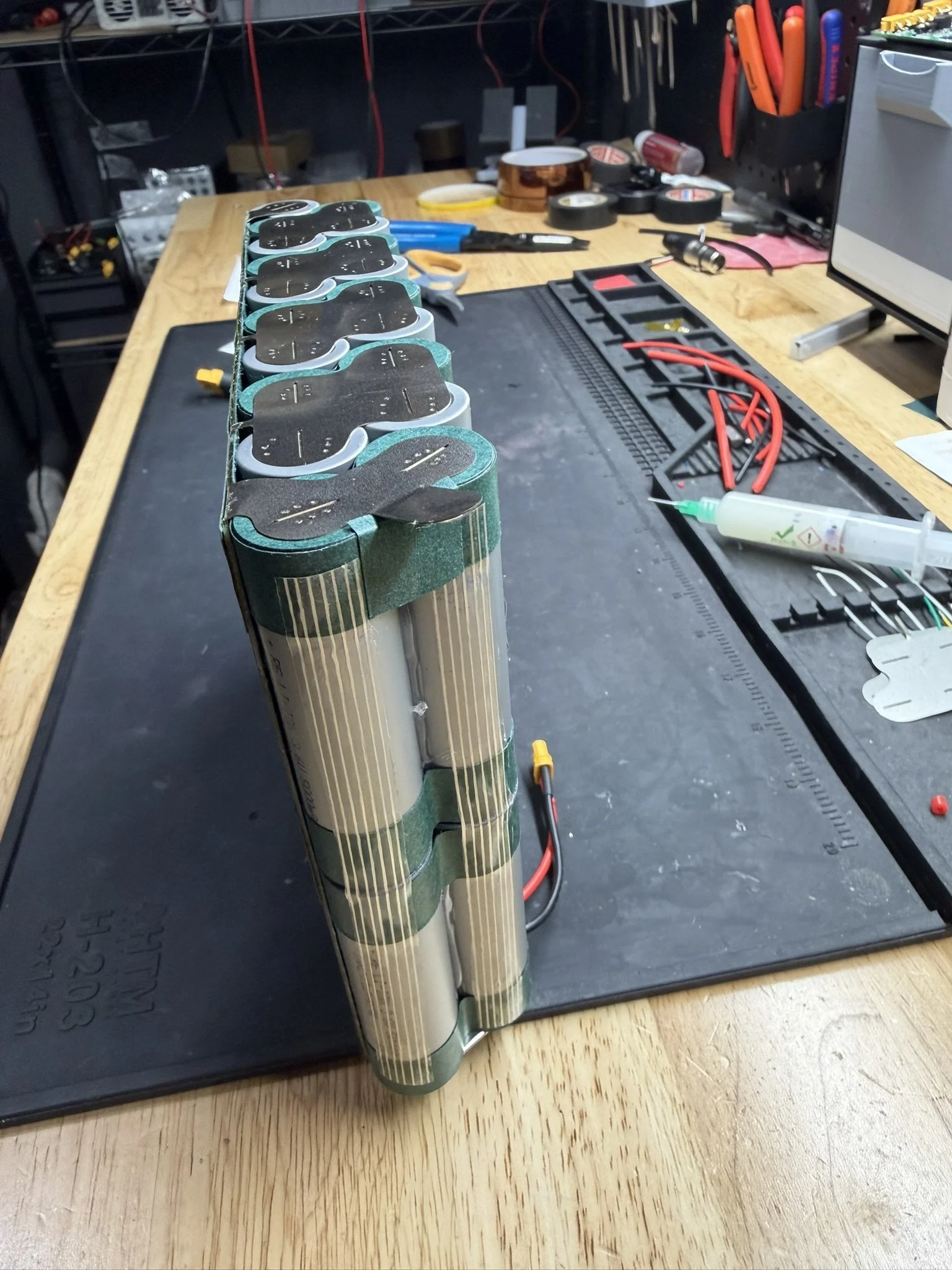
Once the pack halves are aligned, and the divider is in place, I use fiber strapping tape (also linked above in the parts section) to hold the halves together.
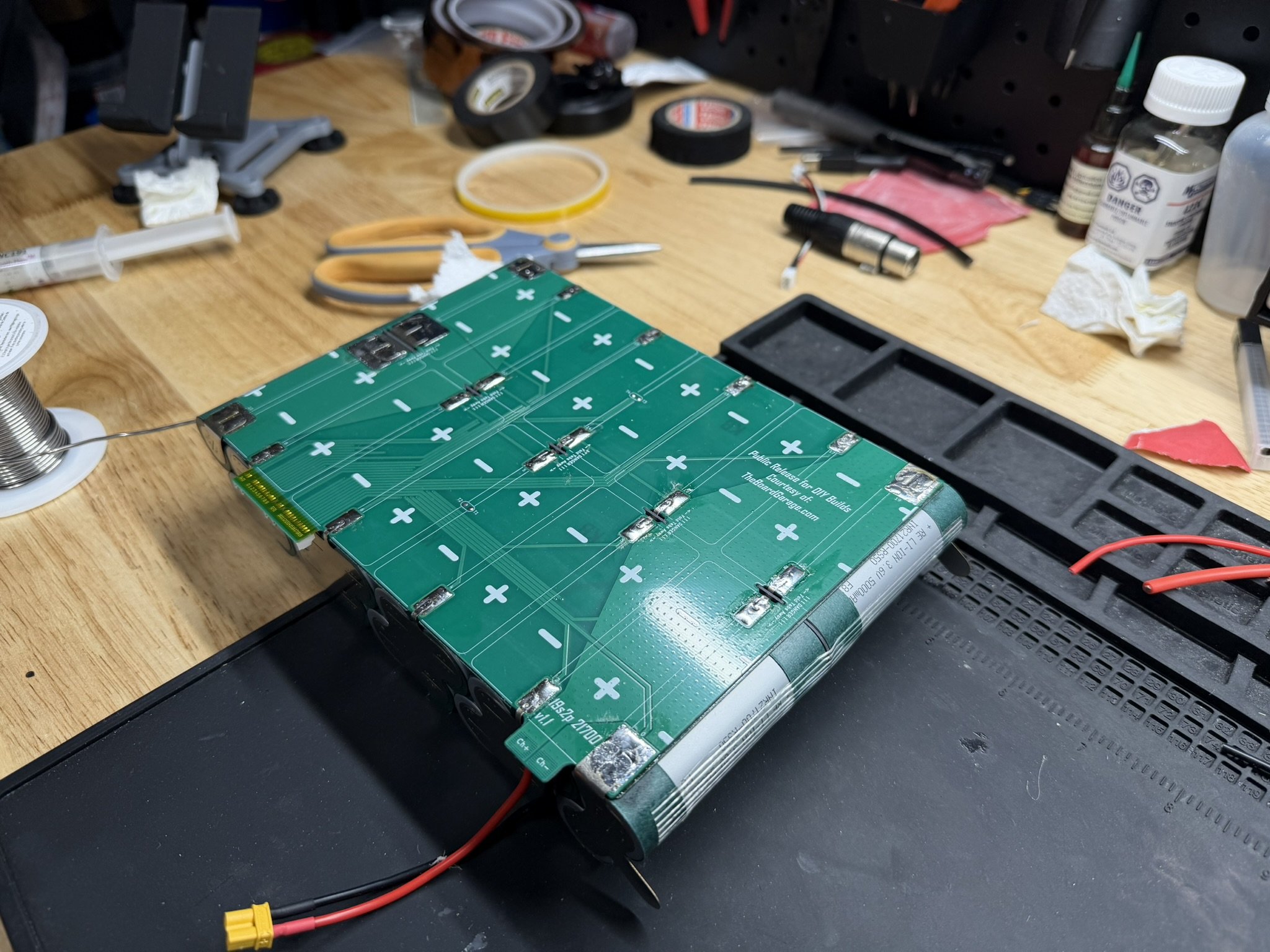
PCB Installation
Once the cell brick is set up, there’s a short 3-step process to getting the PCB on.
First, remove the backing from the adhesive tape.
Then, add some thermal glue to the temperature sensors. I also bend them outward just a bit, so that they bend into place against the cells.
Lastly, carefully align the PCB over the nickel tabs and allow it to key into the center divider keying tabs. For this, I usually center it, and then press down the right side first, allowing that to key in first.
Once the PCB is fully seated, the holes and tabs should all key into each other, the temp sensors should seat, and the adhesive should secure the PCB to the cell brick.
It’s at this point that I CAREFULLY bend the nickel tabs onto their PCB solder pads.
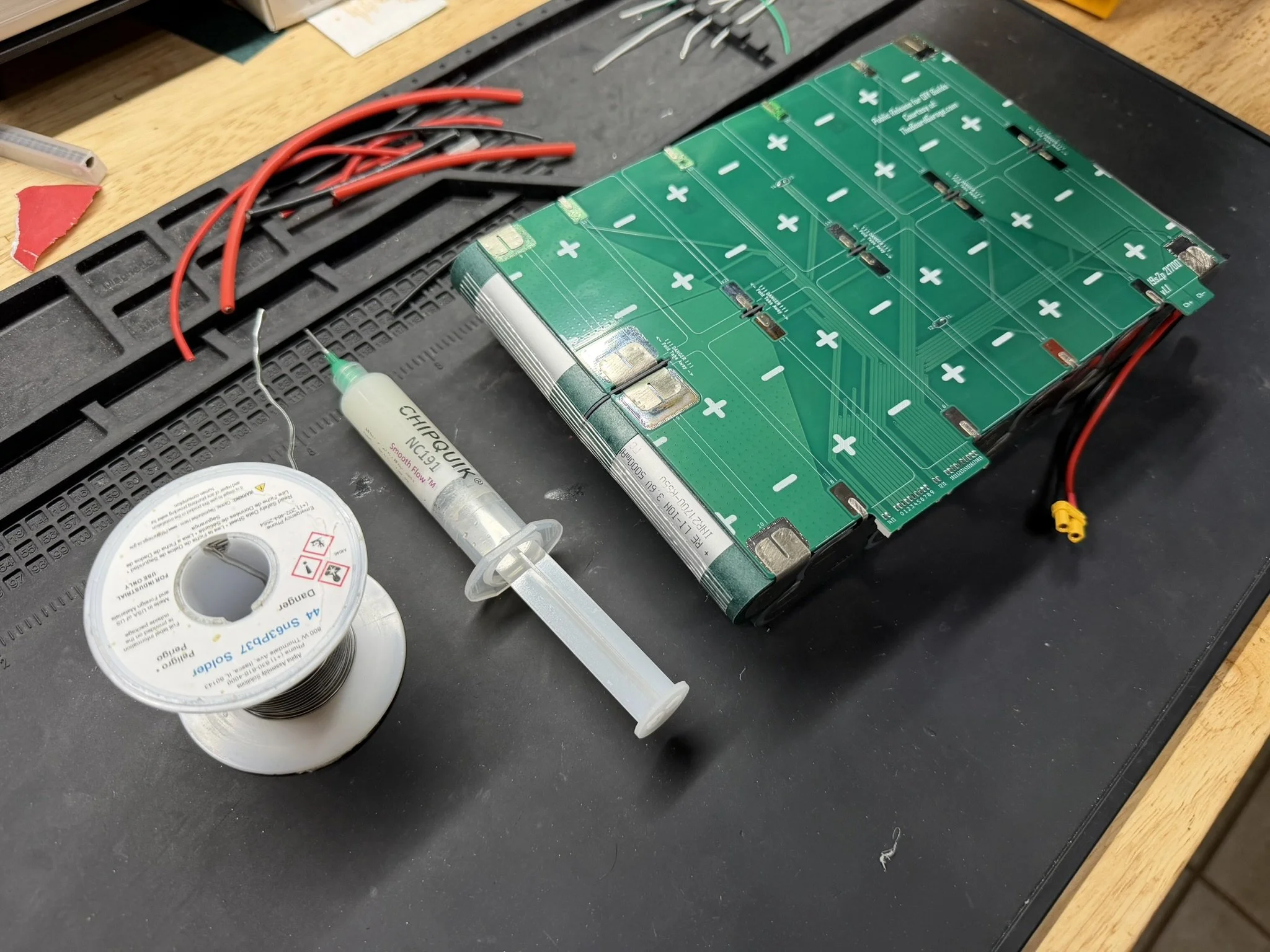
Securing The Nickel To The PCB
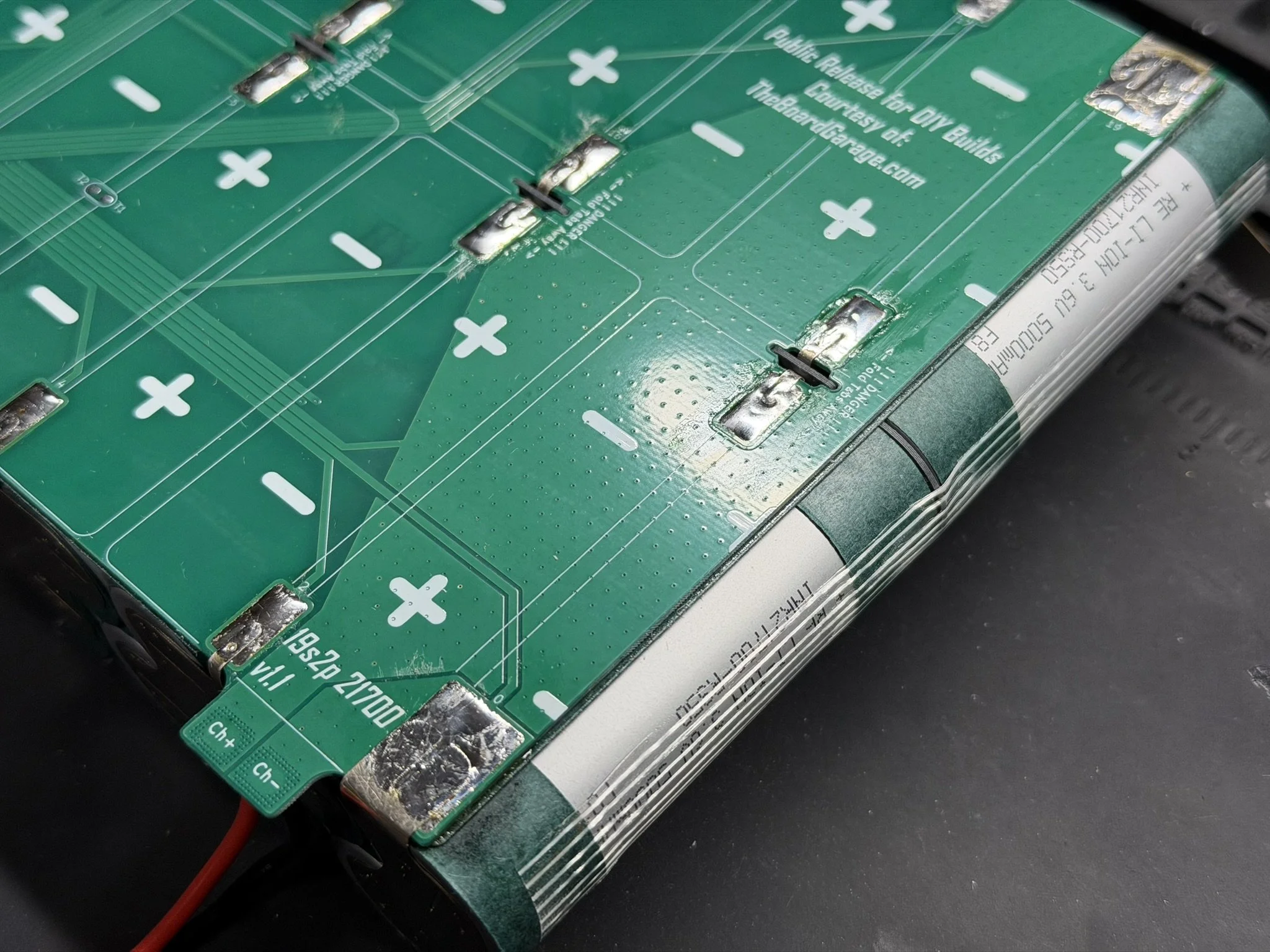
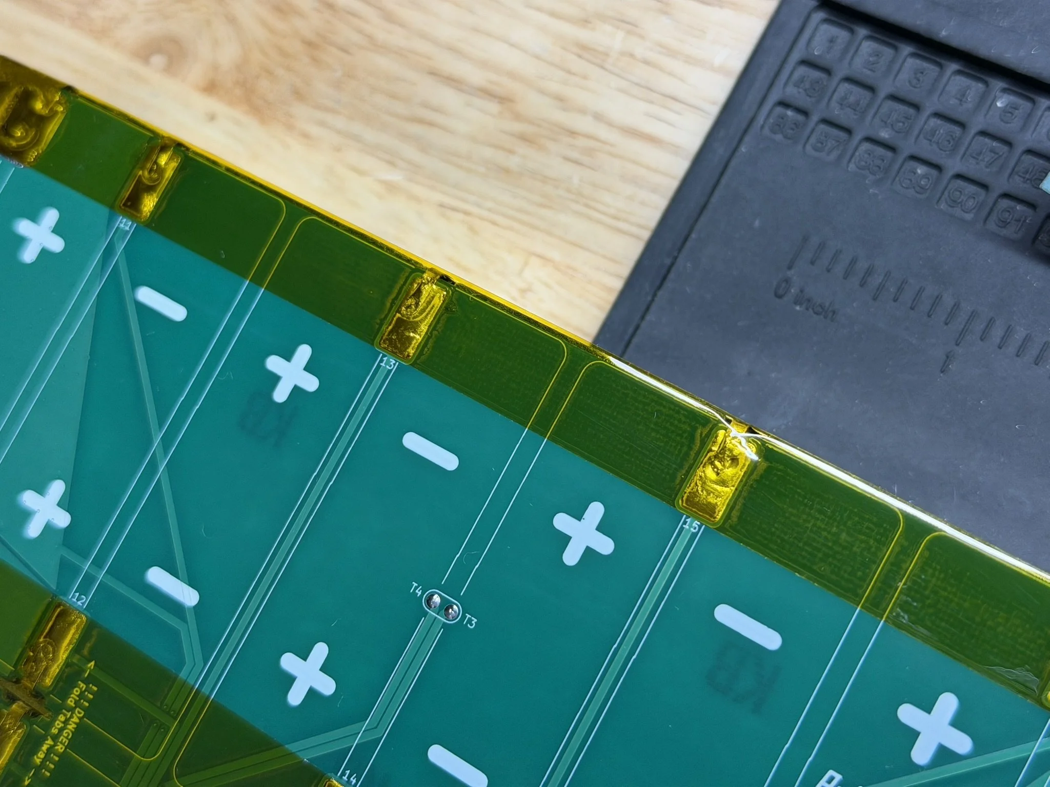
This part of the assembly is divided into 2 joining actions. First, I use the spot welder to tack down the nickel to the PCB solder pads. This is done at about 20% power. It might even take less. This essentially melts the solder that’s on the pad to the nickel, so that it sticks down. Welding this part at higher power will blow out the solder pad and damage the PCB traces. Which, obviously, is bad.

Once the tabs are tacked down onto the PCB solder pads, they get soldered down fully. This part is why scuffing up the nickel tabs is important. The solder will wick down under the nickel tabs, and form a joint between that underside surface and the PCB pad.
When making these solder joints, it’s REALLY important to understand that using an old high wattage soldering iron is not a good idea. I’ve read a lot of builder commentary about 100w-150w irons that reach high temperatures. This might look good on paper, but it’s not appropriate for this work or really for anything like this. What’s important is consistent heat flow. This is why I recommend a cartridge soldering iron or station. Older non-cartridge irons need higher temps to get larger solder joints to melt, and that just burns off flux, damages the parts, and makes for a dangerous joint.
Get the proper tools, or don’t do the job.
For these joints, I add the above linked paste flux, and add just enough solder to wet the pads and nickel. I try to keep the joints low and smooth. Too much solder makes tall pools, and that’s not necessary.
I also use a small fan to keep the surrounding PCB, nickel, and cells cooled off. There’s enough thermal mass around the joints to wick off the majority of the heat, but it’s a smart thing to do anyway. Cells and heat don’t mix well.
After all that, I clean the PCB with the flux cleaner, wipe with a fresh paper towel and isopropyl alcohol, and then dry it off with another paper towel.
Tape & Insulation
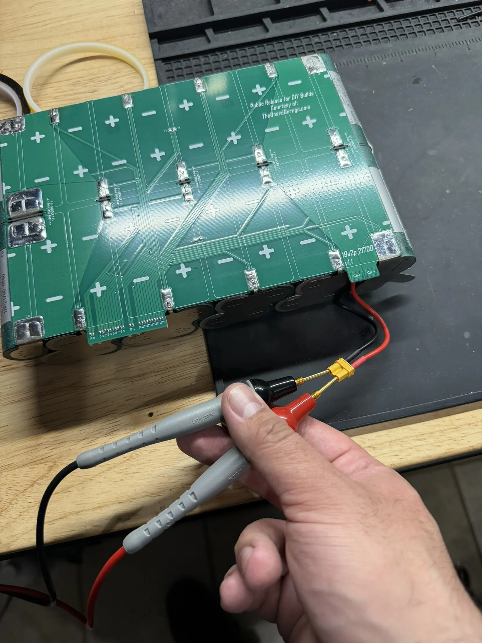
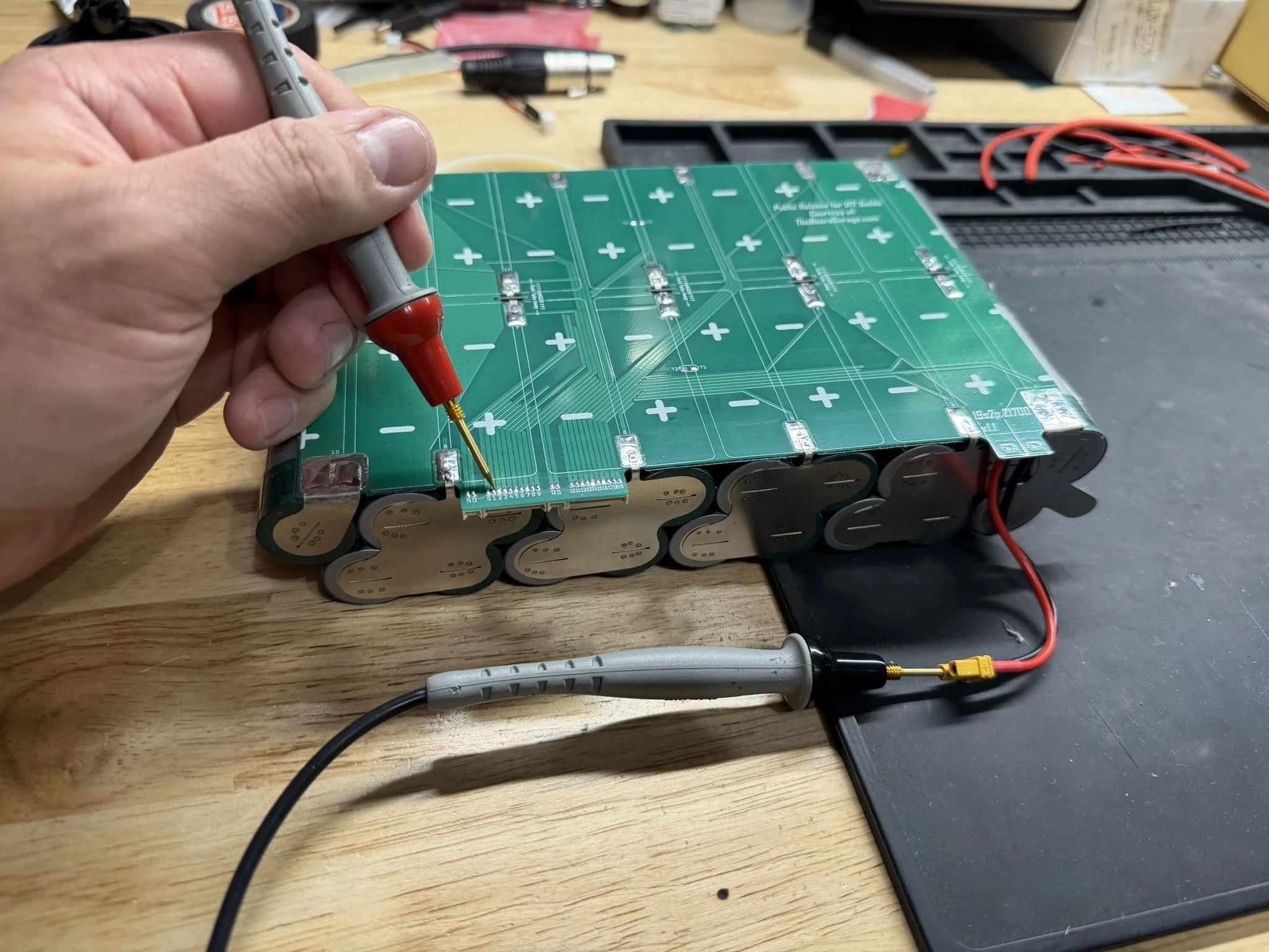
I confirm the connections on the pack with a multimeter at different points of the build (which is general good practice), and so I check the charge circuit and the rest of the connections.
After that, I run a line of Kapton tape over the pads on the PCB to smooth out roughness and prep for the fish paper insulators. Once that’s in place, I carefully align the fish paper shapes to cover over all of the pads and joints.
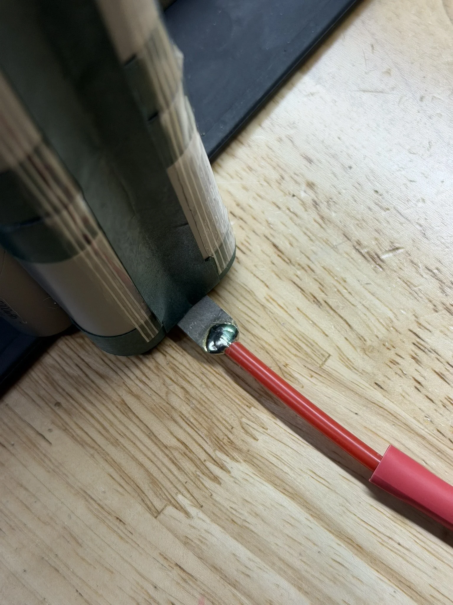
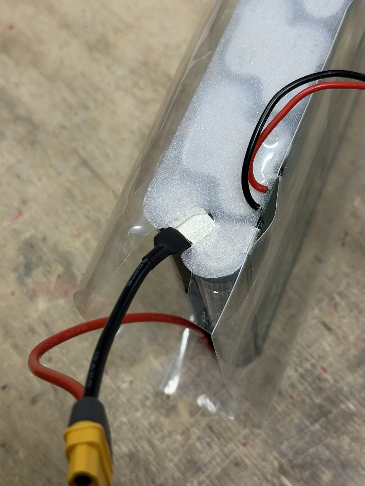
Discharge Wiring Installation
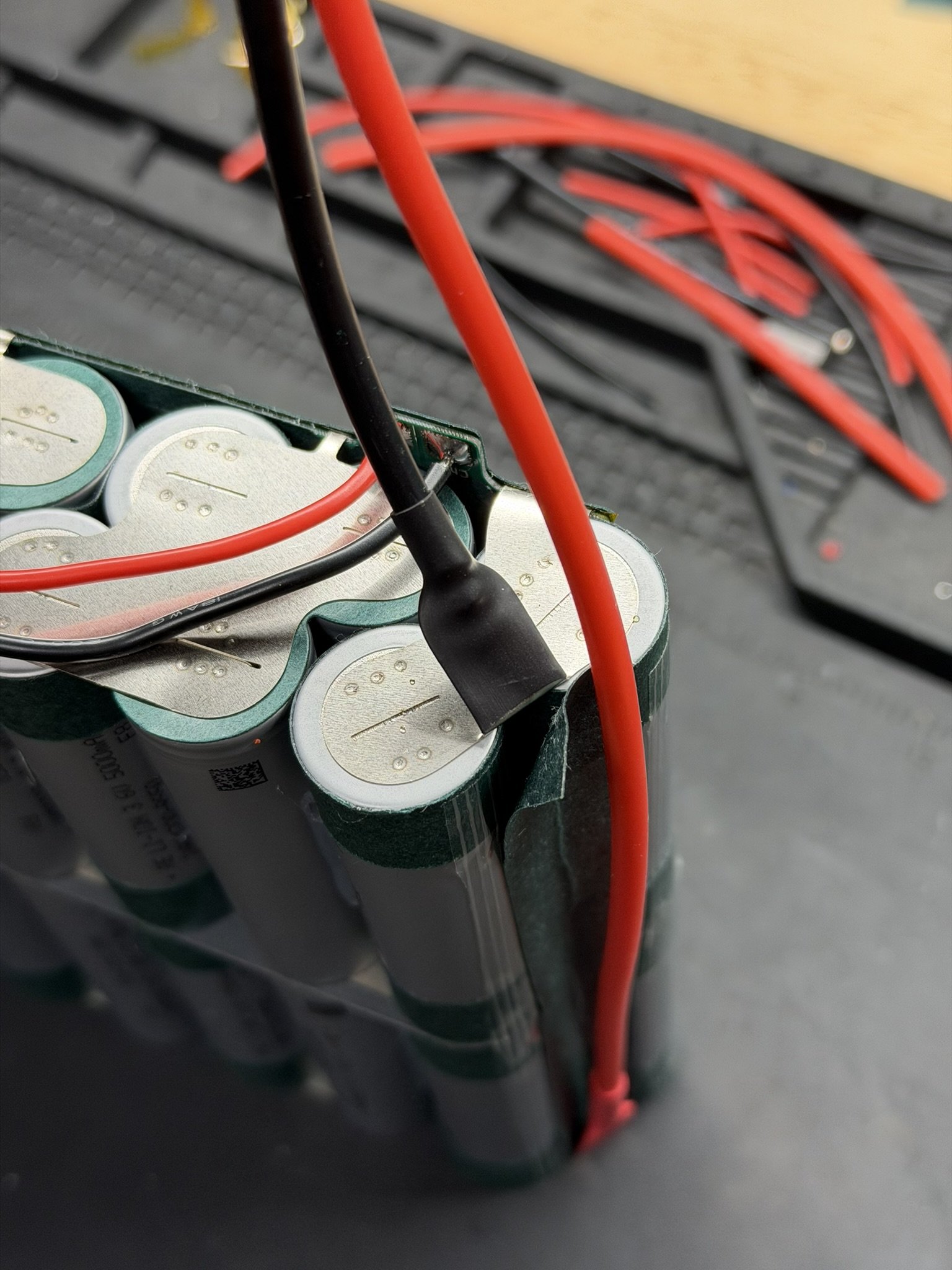
The XT60 wiring harness now gets installed at the terminal nickel. Those surfaces also get scuffed up, and a small blob of solder added. A cut of heat shrink is added to the wires before soldering, so that they can be slid over the nickel.
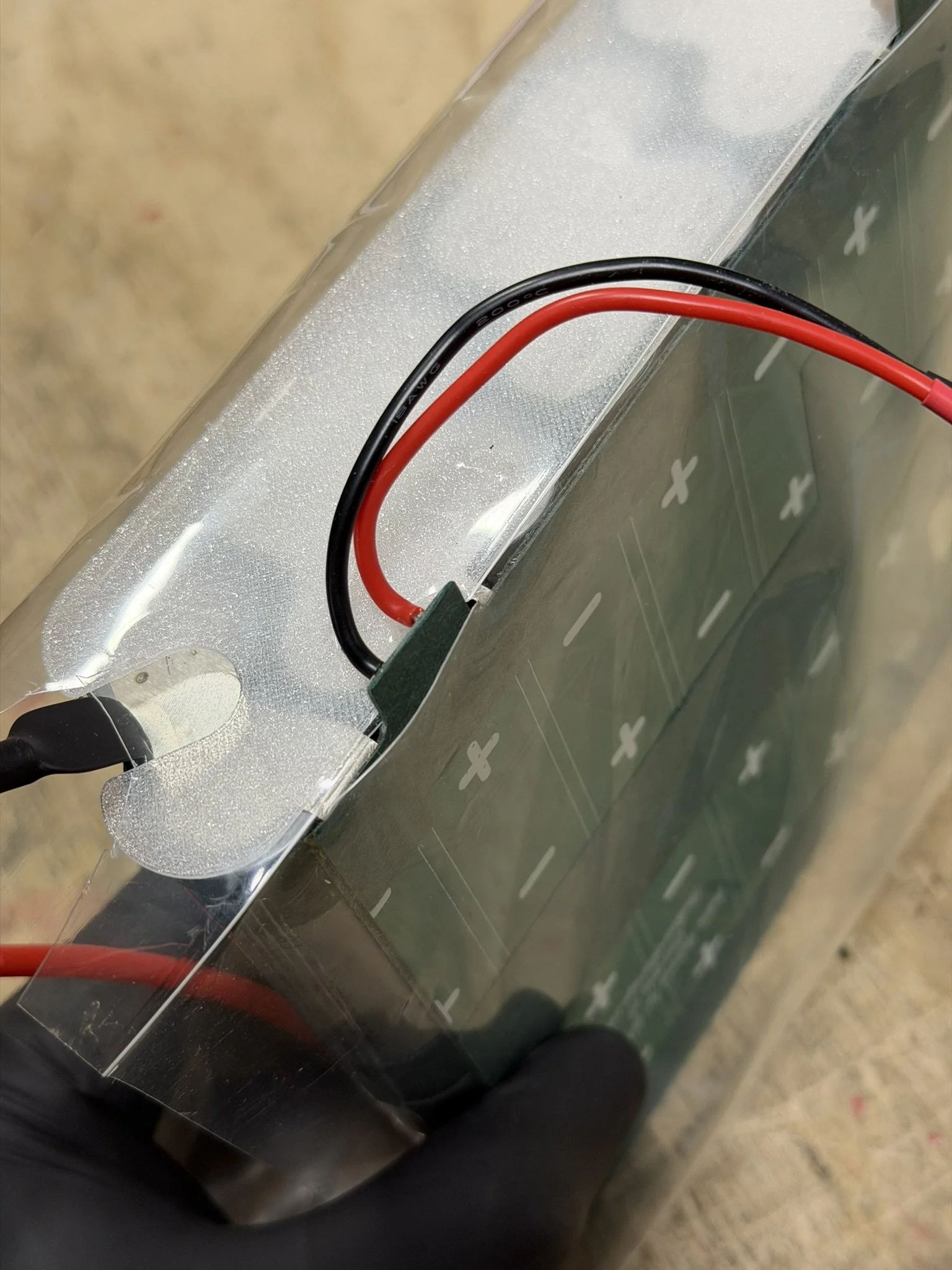
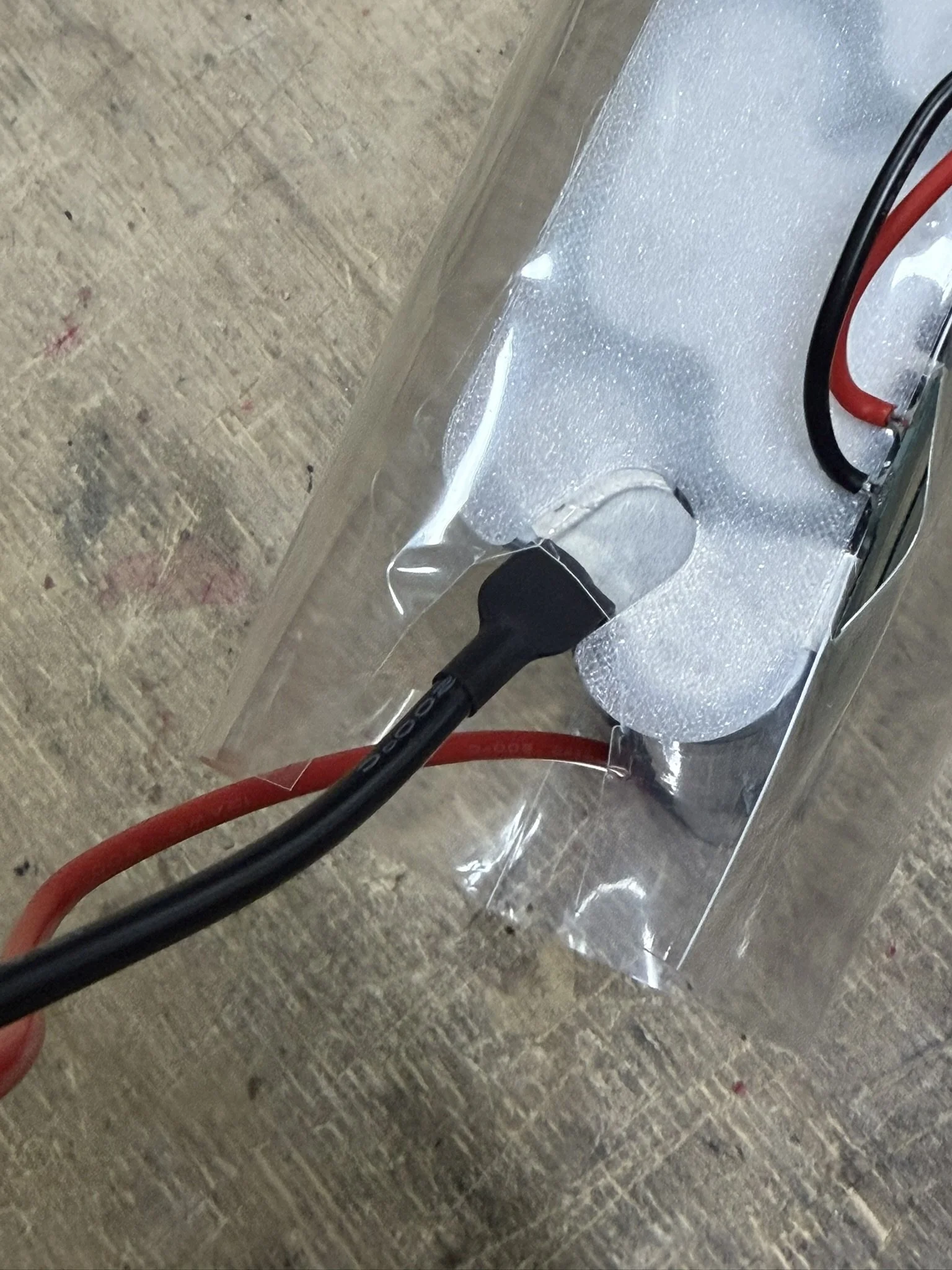
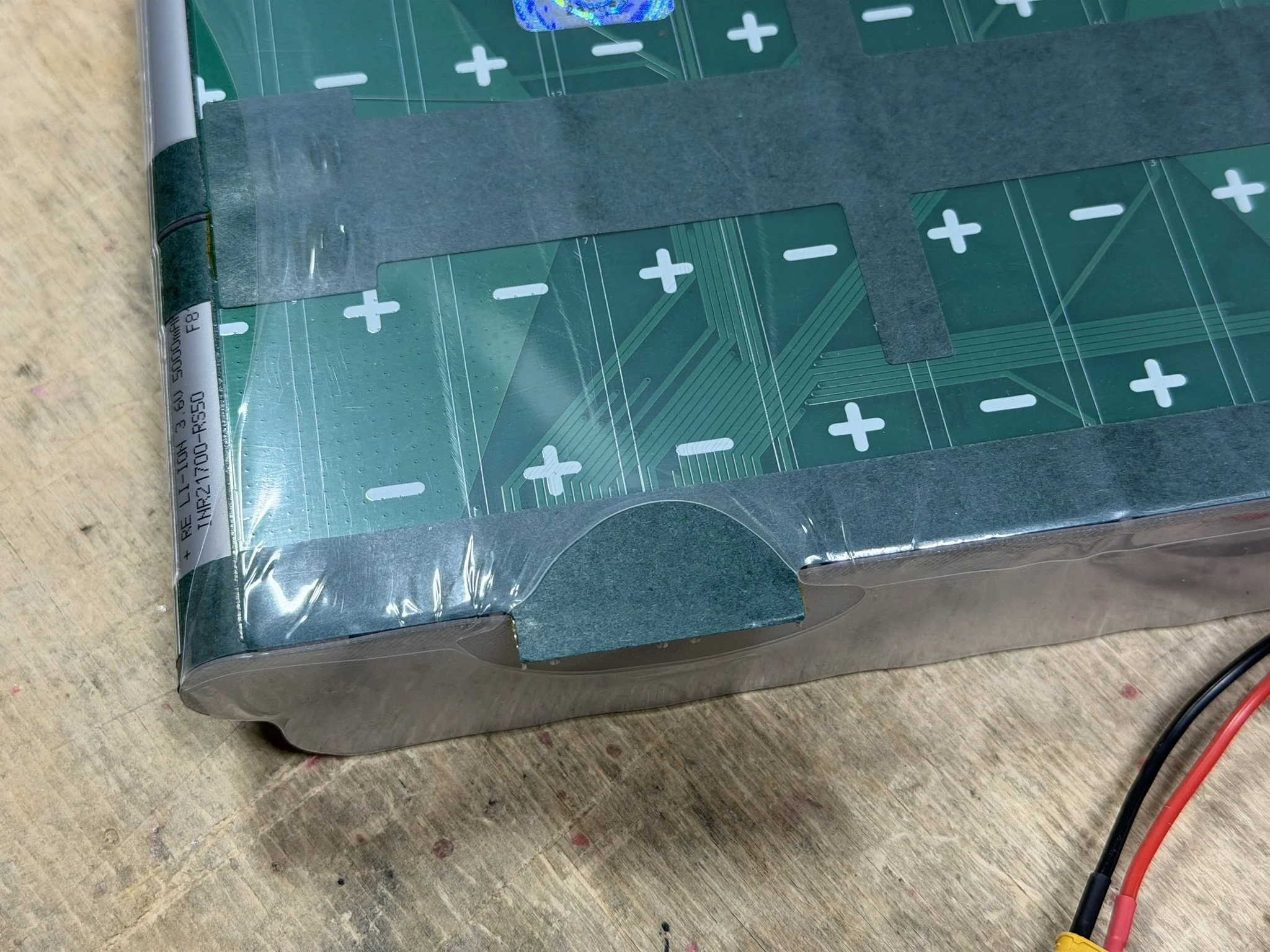
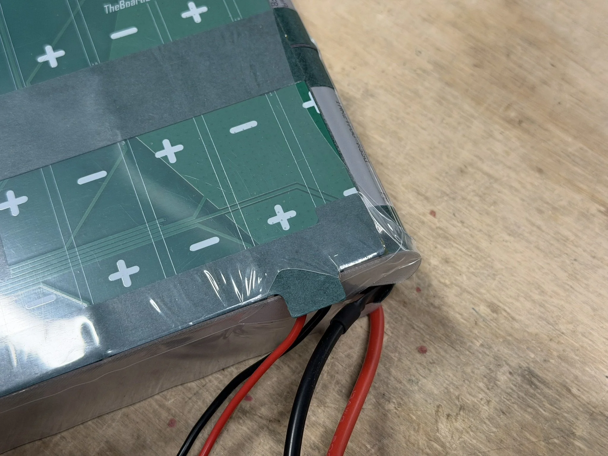
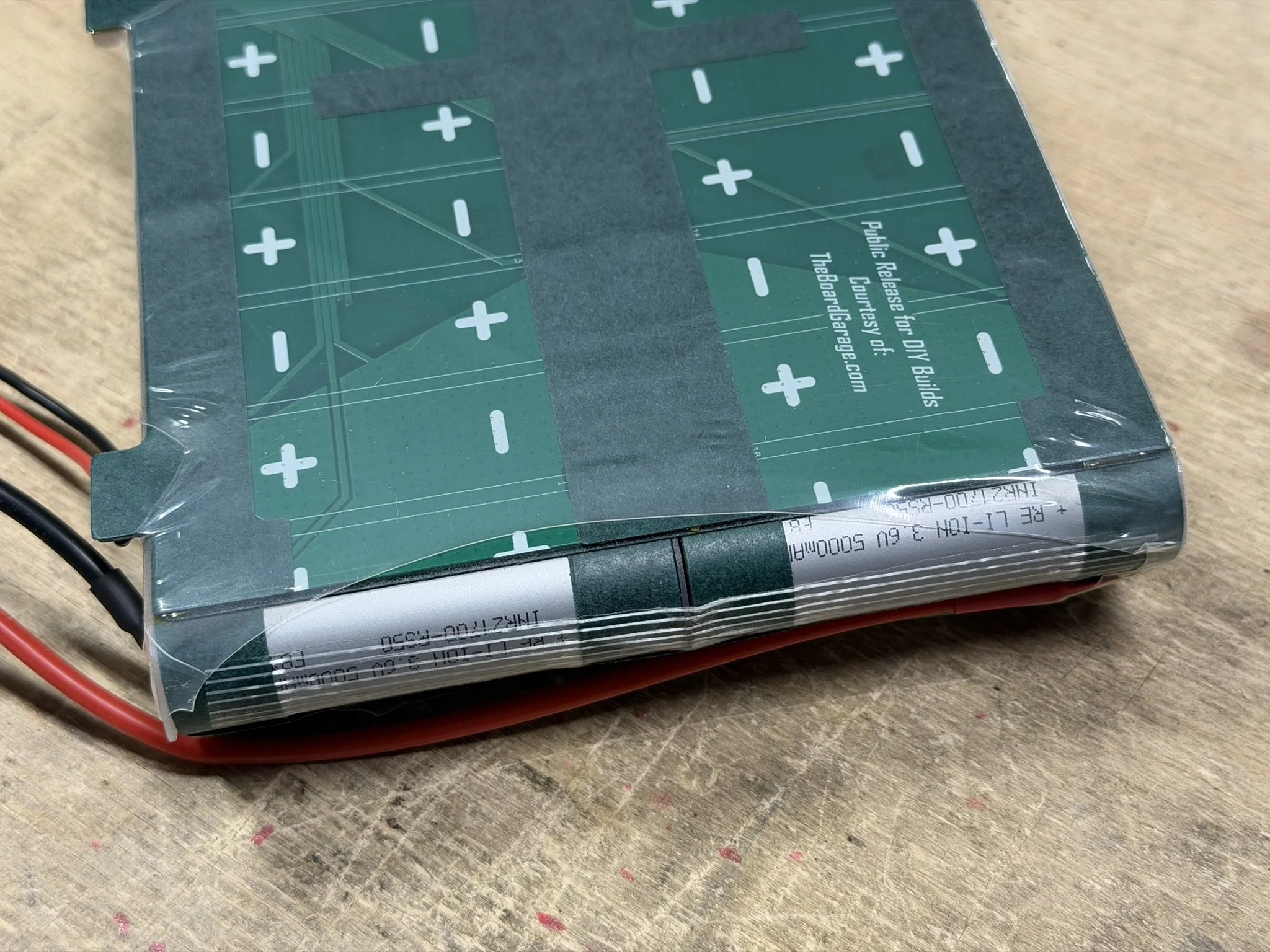
Note in the photos, that there are extra pieces of fish paper in VERY IMPORTANT LOCATIONS.
There is fish paper over the shoulder of the positive terminal cells. The nickel bends over here, and needs protection.
There is fish paper along the side of the pack under the wire.
There is fish paper over the negative terminal connections to protect the positive wiring.
All are pictured below. Also pictured is the placement and bending of the nickel terminals to suit the corner of the pack.
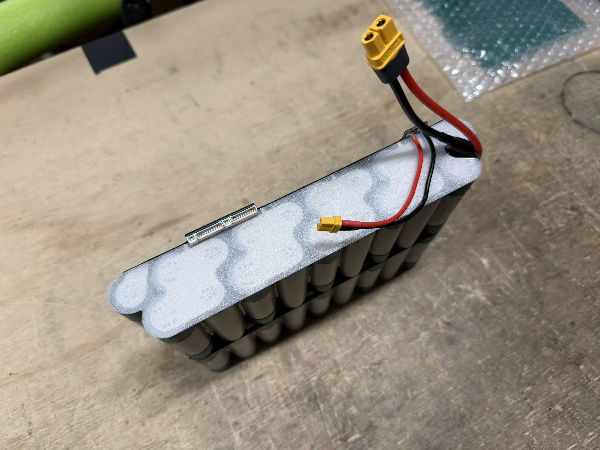
Part 7 - Closing The Pack
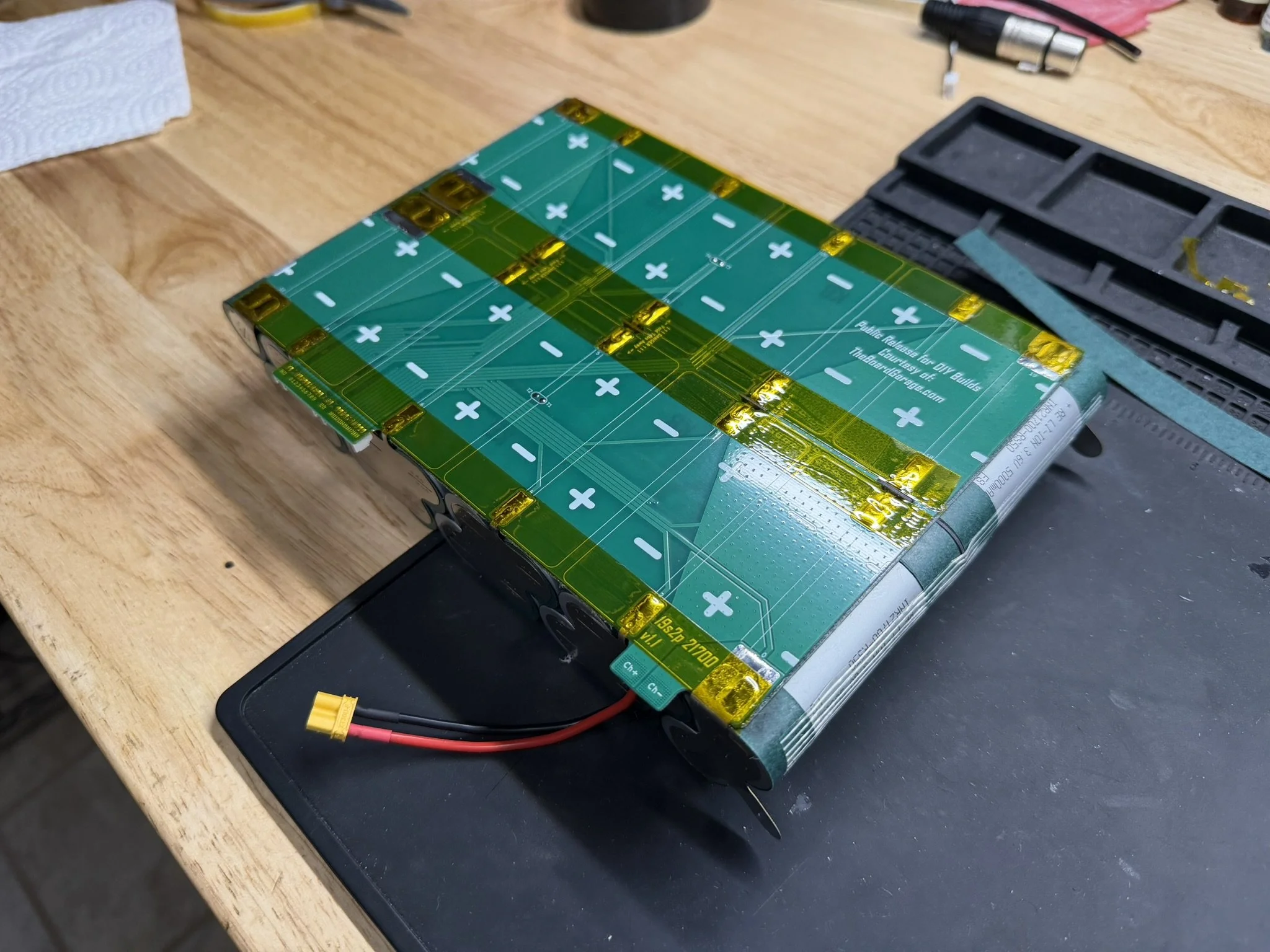
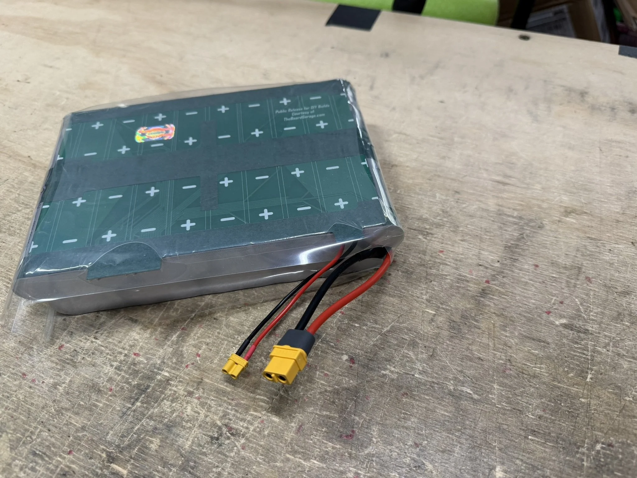
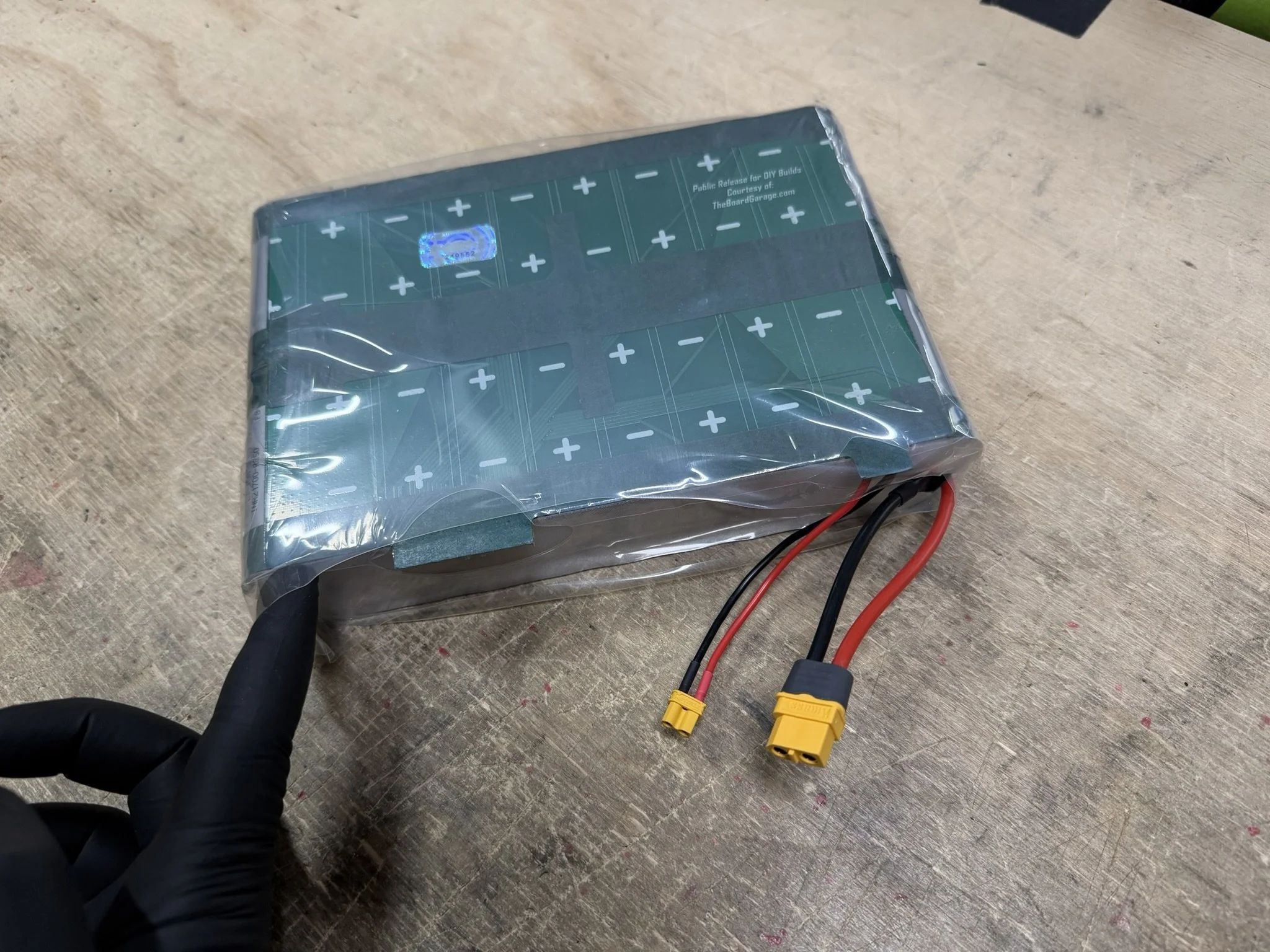
Finishing the pack requires the placement of the printed end caps and then the heat shrinking of the pack.
Note that there end cap with a cut out is placed on the wiring side. The other solid shape goes opposite. The solid shape, I usually print thinner, as mentioned above in the 3D Prints section.
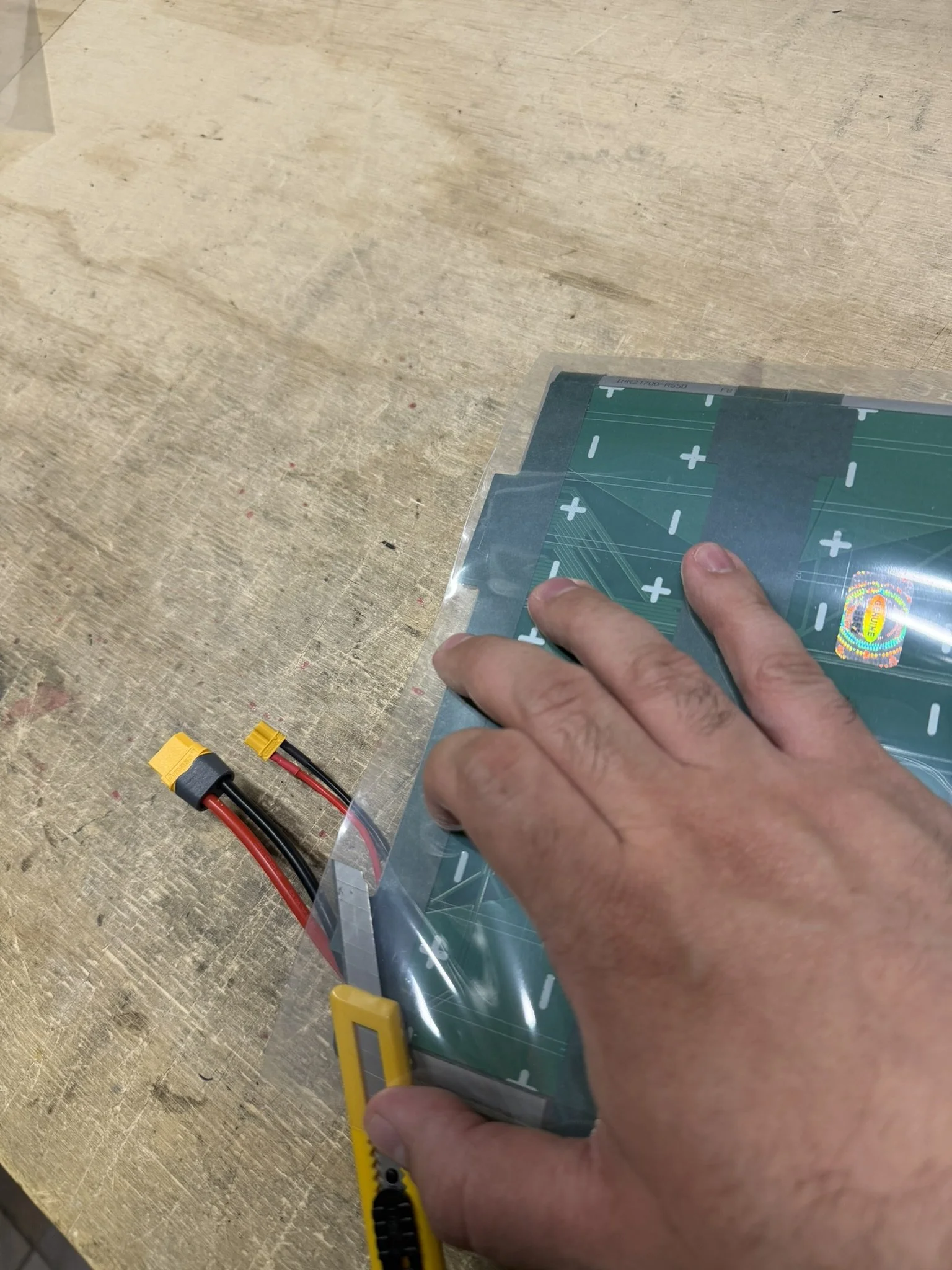
The heat shrink takes some practice, as there’s a heating/shrinking order to things, to get the best results in securing the whole pack together. The image gallery below shows the order of operations, and how I personally go about it.
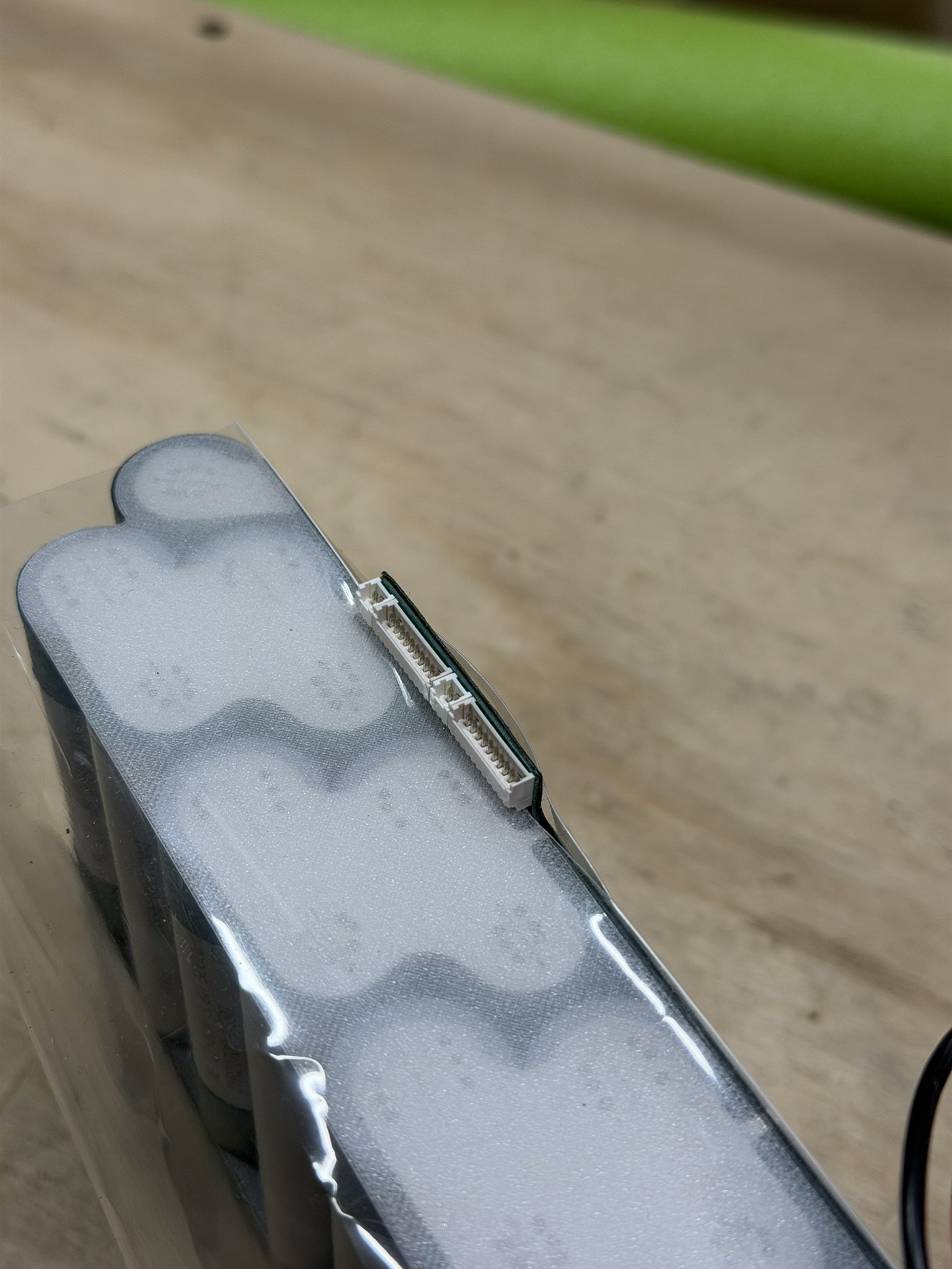
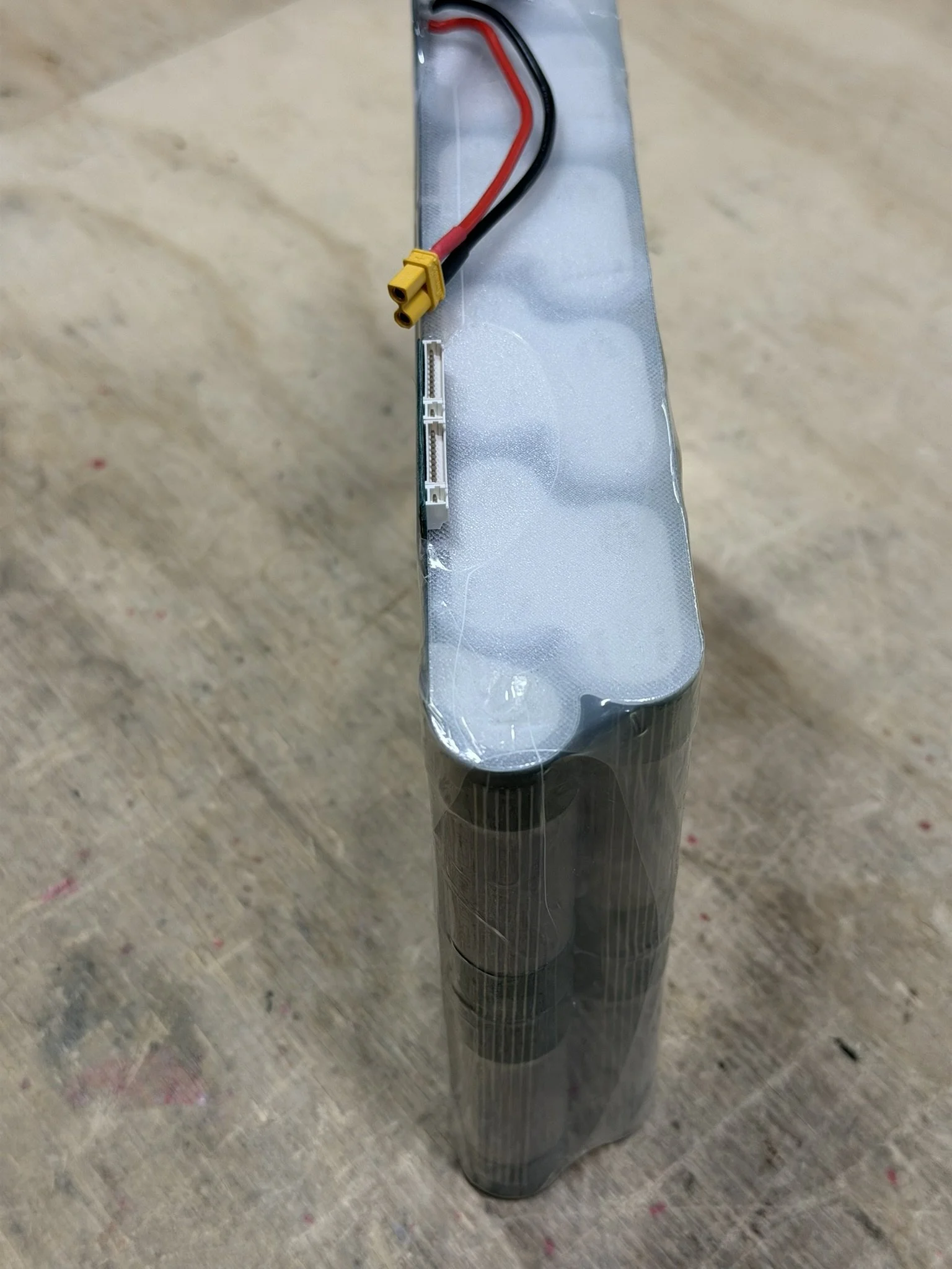
The first layer needs 2 cuts in it to clear the charge circuit wiring as well as the balance connector headers. I line up the fold in the heat shrink, use a thin break off cutter to slice it, and then carefully shrink the wrap around it so it does not tear.
The cross layer of shrink goes around the shoulders, and I have it wrap around the charge wire offshoot to protect those pads and wiring. The balance header area, I shrink it away from as shown below.
Corners get trimmed and flattened .

Part 8 - Installation
Installing this pack requires a couple of noteworthy things, and so that will be covered in detail in a separate article. Specifically, the ENNOID XLITE BMS needs the lower 6-pin JST header removed so the BMS can sit low in the enclosure. I offer those along with this pack in the store, but once those are out, they can be ordered from ENNOID without that connector, so you don’t have to remove it yourself.
In addition to that, the incoming wiring of the enclosure box has to be cleanly managed, and some foam should be added to the pack to keep it biased in a certain direction inside the enclosure. Again, the installation article will cover those items.